

2026-Group 2
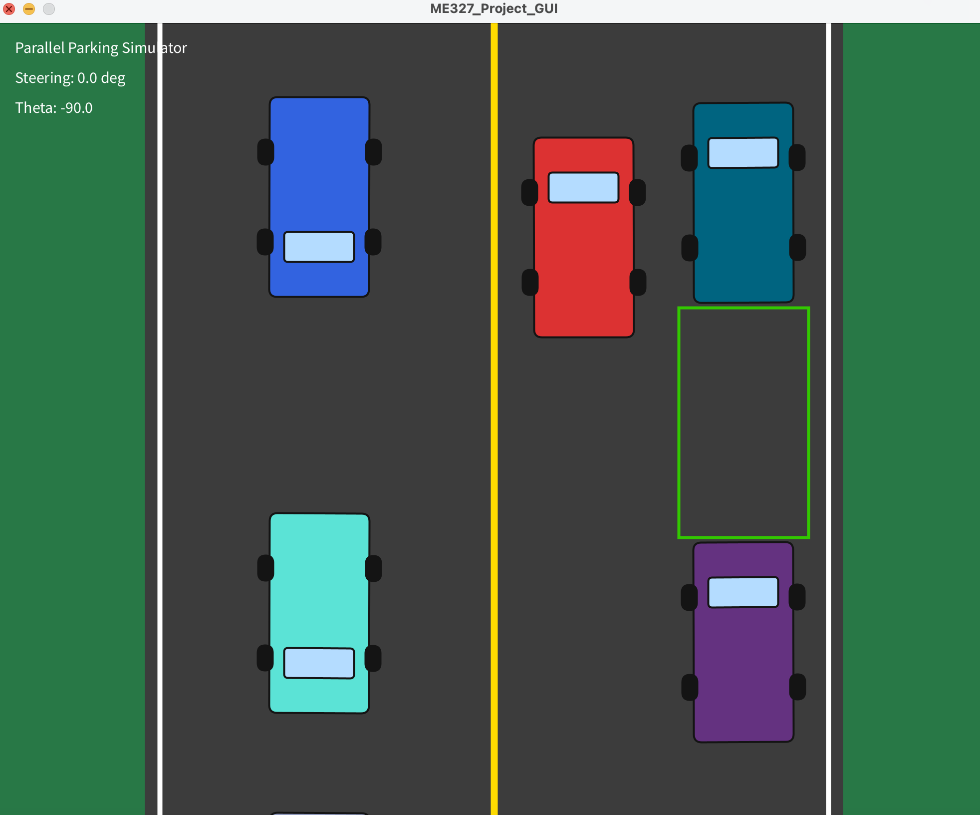
Parallel park the red car
inside the green parking spot!
Parallel Parking Simulator
Project team members: Emma Ziegenbein, Hannah Lin, Amanda Weckerly, Zoe Moskowitz
We developed a virtual parallel parking environment with a haptic steering wheel to help users practice the correct procedure for parallel parking. There are two modes, a training mode and a game mode. The training mode guides the user through the correct steering motions, using force feedback, to effectively parallel park in the green space. Game mode allows users to fully steer the car themselves, and users will only receive haptic feedback (force feedback and vibration) when they collide with the parked cars located in front or behind the parking spot. The graphical user interface (GUI) helps provide visual feedback to users on their location and accuracy in parking in the spot.
On this page... (hide)
Introduction
Learning to parallel park is one of the most universally dreaded milestones in driver education. Despite being a required skill on most driving tests, it remains a leading cause of test failures, minor collisions, and traffic delays among new drivers. The complexity of the maneuver lies in its demands on spatial reasoning, precise timing, and coordinated steering inputs, all of which are difficult to teach through verbal instruction alone. Traditional driver training offers limited opportunities for repetitive, low-stakes practice, and mistakes during on-road training carry real consequences for both the learner and surrounding vehicles.
This project addresses that gap through a haptic parallel parking simulator designed to provide a realistic, informative, and safe training environment. The simulator's primary interface is a motorized steering wheel that delivers force feedback calibrated to simulate realistic steering resistance and vehicle dynamics. Vibration actuators embedded throughout the system provide supplementary tactile cues that communicate collisions with obstacles such as curbs and parked cars, as well as simulate the sensation of a collision. A graphical display renders the vehicle's motion in real time, giving users continuous visual confirmation of their actions. The training experience is structured in two phases. In the first phase, users complete a guided tutorial where the haptic system actively guides them through the correct steering inputs and timing required to execute a parallel park. In the second phase, users practice independently and receive corrective feedback only when they make errors, such as getting too close to a neighboring vehicle. This progression from guided to autonomous practice mirrors established principles in motor learning, allowing users to internalize the maneuver before performing it without assistance. From a controls and dynamics perspective, the system involves several modeling challenges. The steering wheel and vibration motors are modeled as rotational mass-spring systems. Impulse response testing is used to determine realistic deflections and to tune system coefficients so that the haptic feedback feels physically plausible and responsive. Together, these components make the simulator a strong application of human-machine interaction, feedback control, and dynamic systems modeling, all in service of a practical and widely needed driving skill.
Background
Research into haptic feedback for driving simulation and driver assistance has grown substantially over the past decade, with studies consistently showing that well-designed tactile and force feedback systems improve both performance and user experience. The following works are most directly relevant to the design of our simulator. Murphy et al. (2026) examined the effect of force feedback and vibrotactile feedback on performance and immersion in sim racing steering wheels. Their study had experienced sim racers complete timed laps under varying combinations of force and vibration feedback intensities. A key finding was that moderate force feedback improved lap times and steering precision compared to no feedback at all, while excessively high force levels actually degraded performance by making the wheel harder to control. Vibrotactile feedback did not produce measurable performance gains but was strongly preferred by participants because of the sense of immersion and realism it added. This result directly informs our design: force feedback should be tuned to a moderate, functional level, while vibrotactile feedback plays a complementary role in conveying environmental texture and collision events rather than guiding precise steering behavior. Balachandran et al. (2015) developed a shared-control steering system that uses a Model Predictive Control (MPC) framework to generate predictive haptic feedback for obstacle avoidance. Rather than waiting for an imminent collision to alert the driver, the system anticipates future collision risk based on the vehicle's predicted trajectory and progressively increases steering wheel resistance as that risk grows. Experimental validation on a steer-by-wire vehicle showed that drivers using this system began corrective steering earlier and more smoothly than those without haptic guidance. This work strongly supports our approach of using graduated haptic feedback, increasing vibration intensity and steering resistance as the simulated vehicle approaches a curb or parked car, rather than relying on a sudden jerk or alert only at the moment of contact. It also validates the broader concept of using steering wheel force as a way to communicate spatial hazard information to a driver. Petermeijer et al. (2015) conducted a comprehensive literature survey on haptic driver support systems, synthesizing findings across guidance systems that actively assist with steering or pedal inputs, and warning systems that deliver tactile alerts when a hazard is detected. Their review found that haptic feedback reliably reduces driver workload and improves reaction time, largely because tactile information is processed quickly and does not compete with the visual demands already placed on a driver. However, they also identified an important failure mode: when the haptic system's suggested action conflicts with the driver's intended action, the feedback can be counterproductive and actually increases errors. They conclude that haptic signals need to be calibrated to be noticeable without being distracting, and that adaptive systems tuned to individual driving behavior are a promising direction for future work. For our simulator, this highlights the importance of tuning feedback thresholds carefully and making sure the guidance phase of our tutorial feels instructive rather than like it is fighting the user's inputs. These papers establish a solid foundation for the use of haptic steering feedback in driving training contexts, validates our choice of both force and vibrotactile modalities, and offers practical guidance on how to structure and tune feedback for maximum effectiveness.
Methods
Hardware Design and Implementation
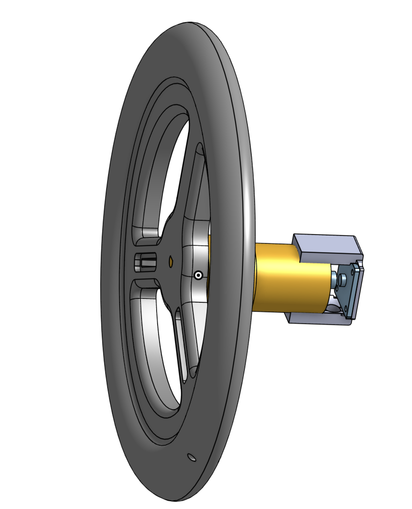
The project was built with a physical steering wheel interface and a GUI designed with Processing. The hardware setup consisted of a 3D-printed steering wheel mounted to a fixed base. The steering wheel had cutouts on each side where vibration motors were placed and secured with hot glue. A DC motor with at 49:1 geared output was used with direct drive to apply torque to the steering wheel and a magnetic encoder was used to measure wheel position. An encoder holder was designed to hold the encoder exactly 2 mm away from the magnet on the end of the motor shaft to ensure accurate encoder readings. We also designed a 3D-printed casing to secure all of the electronics.
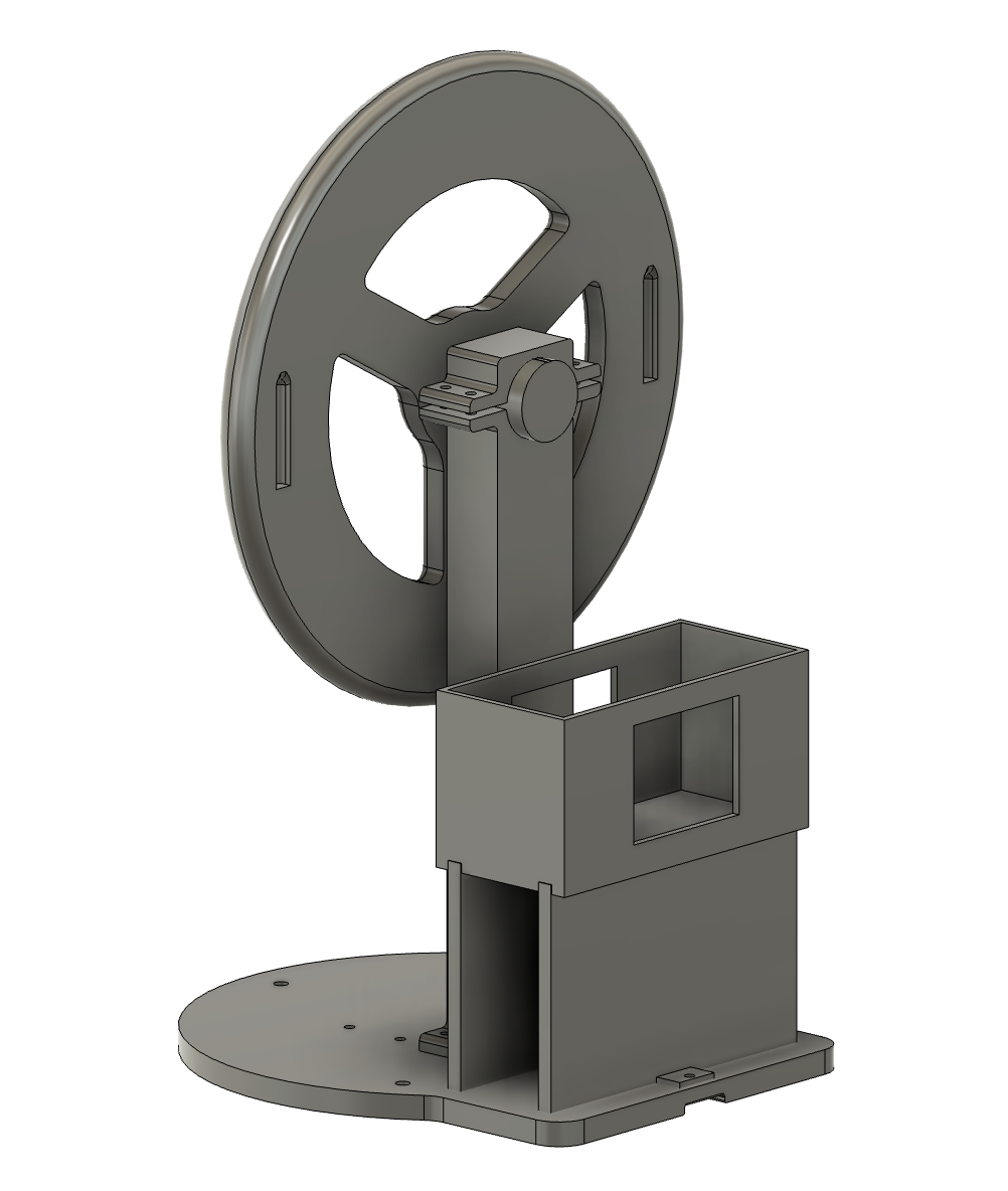
The steering wheel was mounted vertically on the base so the user could rotate it in the same manner as a real steering wheel. The two vibration motors were embedded for tactile feedback and the base had 3 buttons for game control. The DC motor controlled via PWM allowed the Arduino to apply torque in either direction which simulated a �kick� during collision feedback and guided the user during training mode.

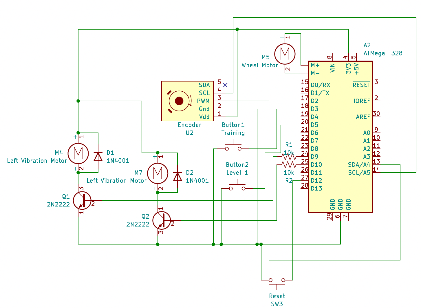
The magnetic encoder communicated with the Arduino over I2C. Registers 0x03 and 0x04 were read and combined into a raw position value which was then converted into a continuous steering angle. Since the encoder count resets after one full revolution, we implemented rollover detection such that multiple wheel rotations could be tracked continuously.
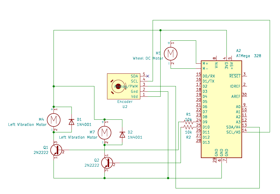
We wired the encoder to the Hapkit Board (ATMega 328) to allow for I2C communication by following the schematic diagram shown. Because the vibration motors required about 60 mA of current and the Arduino PWM pins can supply a maximum of 40 mA, we added the 2N2222 transistor between the board�s pins and the vibration motors so that the board acts as a switch and more current can be supplied. We also added a diode across the vibration motor pins to protect the transistor and board from spikes of voltage across the motor during switching.
System Analysis and Control
The system used an Arduino sketch for hardware control and a Processing sketch for the graphical simulation. The Arduino handled the encoder reading, motor output, vibration output, button detection, mode control, and serial communication. Processing handled the visual simulation which included the road, parked cars, parking spot, moving car, oncoming traffic, and parking success condition.
The Arduino and Processing communicated over serial connection at 115200 baud. During operation, the Arduino sent the current steering wheel angle to Processing at approximately 60Hz. Processing then read this steering value and used it to update the moving car angle. Processing also looked for button messages from the Arduino to start training mode, game mode, or reset the simulation.
The Arduino code was organized around three main states: IDLE, TRAINING, AND LEVEL1. In IDLE, the system waited for user input and kept the vibration motors off. In TRAINING, the DC motor applied a guiding torque to help the user follow a predefined steering path. Each phase of the steering path had a target steering angle and duration. The Arduino compared the measured steering angle to the target angle and calculated an error. The motor then applied a torque proportional to this error which acted like a virtual spring that pulled the steering wheel toward the desired position. A small deadband was also included so the motor would not chatter when the wheel was close to the target. In LEVEL1, the steering wheel was not guided, so the user controlled the car freely. Collision feedback was active in LEVEL1. The collision system modeled the moving car and parked car as oriented bounding boxes. The moving car rotated with the simulated vehicle heading while the parked cars remained fixed. This allowed us to detect collisions using the Separating Axis Theorem. If the moving car overlapped with one of the parked cars, the Arduino triggered collision feedback which consisted of a short motor kick in the opposite direction and a continuous vibration that was active as long as a collision was occurring.
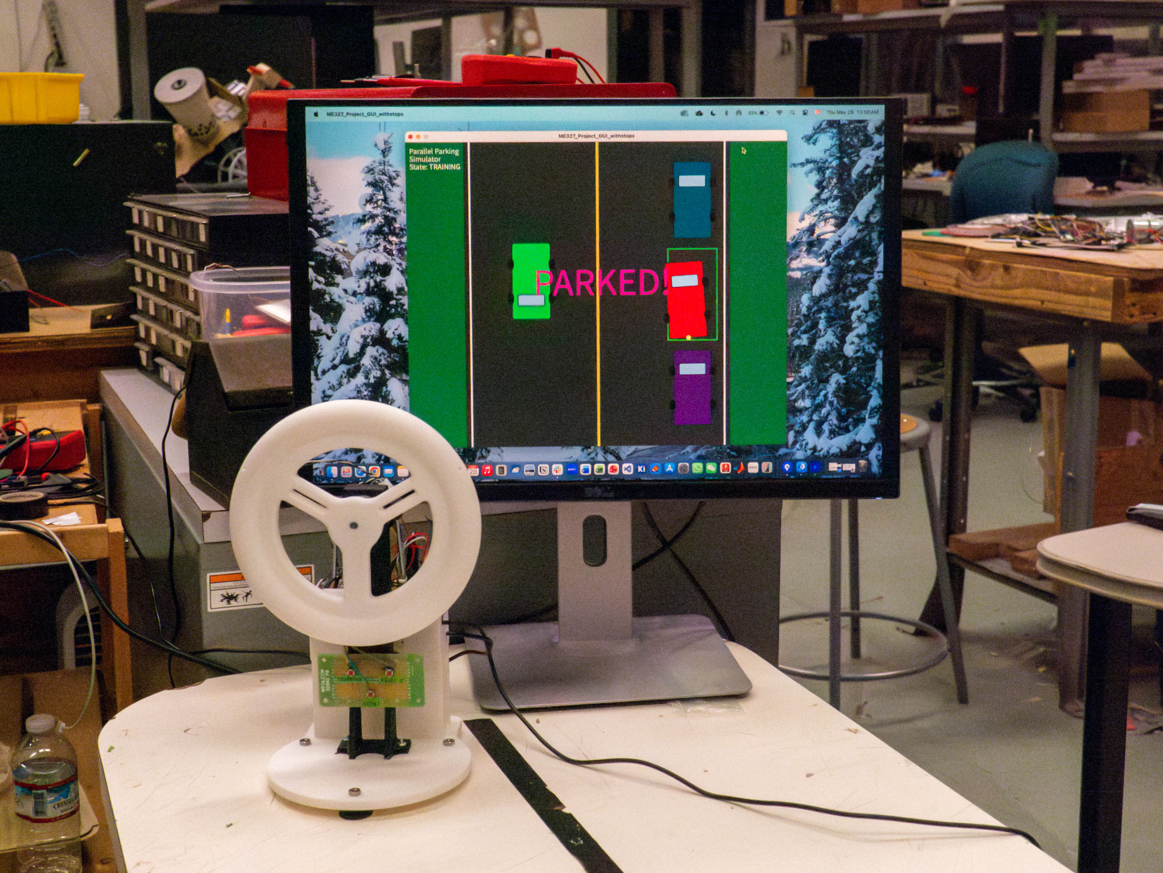
We simulated the vehicle using a simple bicycle model, which is a good approximation of how cars move in real life when backing in at slow speeds. The physical steering wheel angle measured by the encoder was converted into a tire angle using a steering ratio of 1:15. This prevented small physical motions from making the simulated car turn too aggressively. The tire angle was also constrained to a safe range such that the car�s motion, which involved a tangent calculation, would remain stable. During each loop, Processing would read the latest steering angle, convert it into a tire angle, update the car heading, and update the car�s position, redrawing the car on the screen accordingly. Processing also checked whether the user had successfully parked. The success condition was based on the back of the car entering the bottom three pixels of the parking spot. Once the car reached this target area, Processing stopped the car and displayed �PARKED!� on the screen which sent the Arduino into IDLE state.
Kinematic System and Controls Analysis
Steering Trajectory Kinematic Analysis
The steering trajectory for the parallel parking maneuver was generated using the kinematic bicycle model, which approximates the vehicle as a single front steering wheel and a single rear wheel. The vehicle dynamics are given by
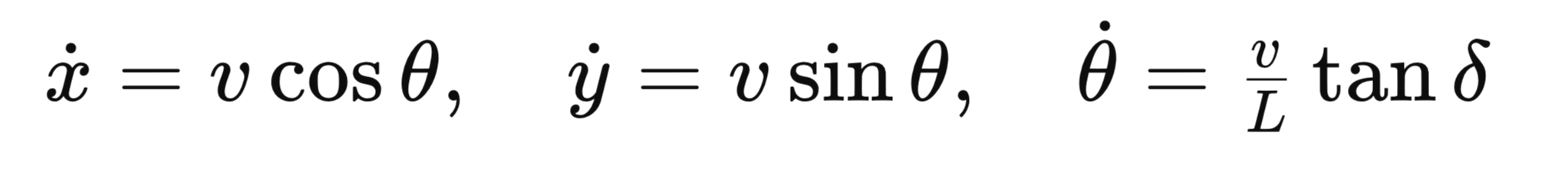
where x and y denote the vehicle position, θ is the vehicle heading, v is the vehicle velocity, L is the wheelbase, and δ is the front-wheel steering angle. Steering wheel commands were converted to front-wheel steering angles through the simulator steering ratio. Previous work has shown that parallel parking maneuvers can be effectively approximated using a biarc trajectory consisting of two circular arcs connected by a transition segment. Using this concept as a starting point, the parking maneuver was decomposed into a sequence of piecewise-constant steering commands corresponding to (1) an initial straight reverse approach, (2) a first turning arc into the parking space, (3) a counter-steering arc to align the vehicle with the curb, and (4) a final wheel-centering phase. For a constant steering angle, the bicycle model follows a circular path with turning radius

and the resulting heading change over a steering phase of duration t is

Using the desired heading changes associated with each parking arc, along with the constant reverse velocity used in the simulator, the duration of each steering phase was selected to produce the required vehicle orientation changes. The resulting steering profile was implemented as a piecewise-constant sequence of steering-wheel-angle commands and dwell times, producing a parking trajectory that approximates the geometric biarc solution while remaining simple to implement in real time. The full piecewise sequence went as follows,
| Phase | Time Interval (s) | Steering Wheel Angle (rad) | Maneuver Description |
|---|---|---|---|
| 1 | (0 < t < 2.5) | 0.0 | Straight reverse approach |
| 2 | (2.5 < t < 4.0) | -0.8 | Initiate turn into parking space |
| 3 | (4.0 < t < 9.0) | -2.1 | Primary backing arc |
| 4 | (9.0 < t < 19.0) | 0.0 | Straight transition segment |
| 5 | (19.0 < t < 21.5) | 1.5 | Begin counter-steering |
| 6 | (21.5 < t < 25.2) | 2.4 | Counter-steering arc for alignment |
| 7 | (25.2 \le t < 30.2) | 0.0 | Final wheel centering and parking |
Controls Analysis
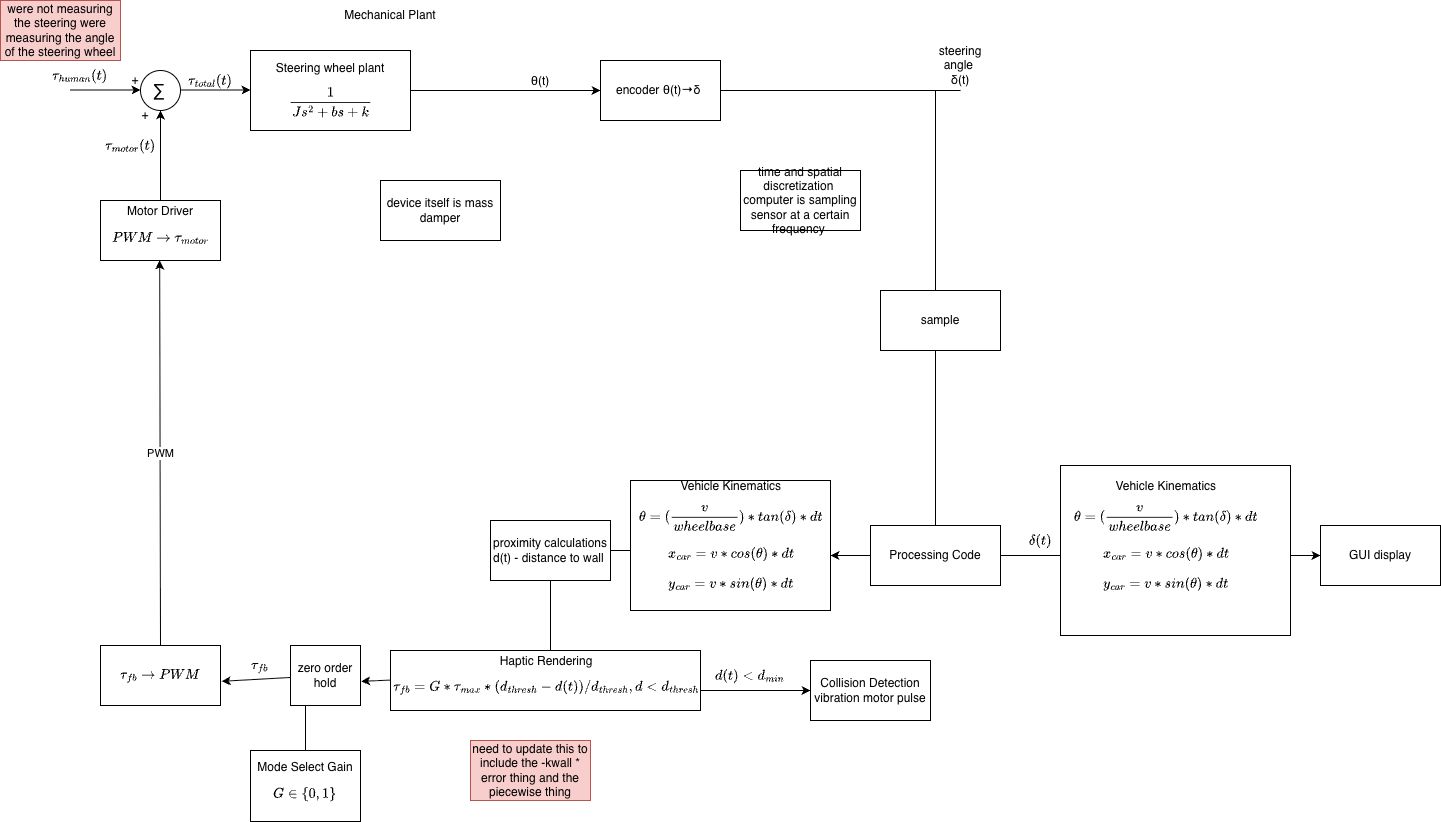
Below is a block diagram of our steering system, which includes the vehicle dynamics, human input, path error computation, and nonlinearities between the human-computer interaction.
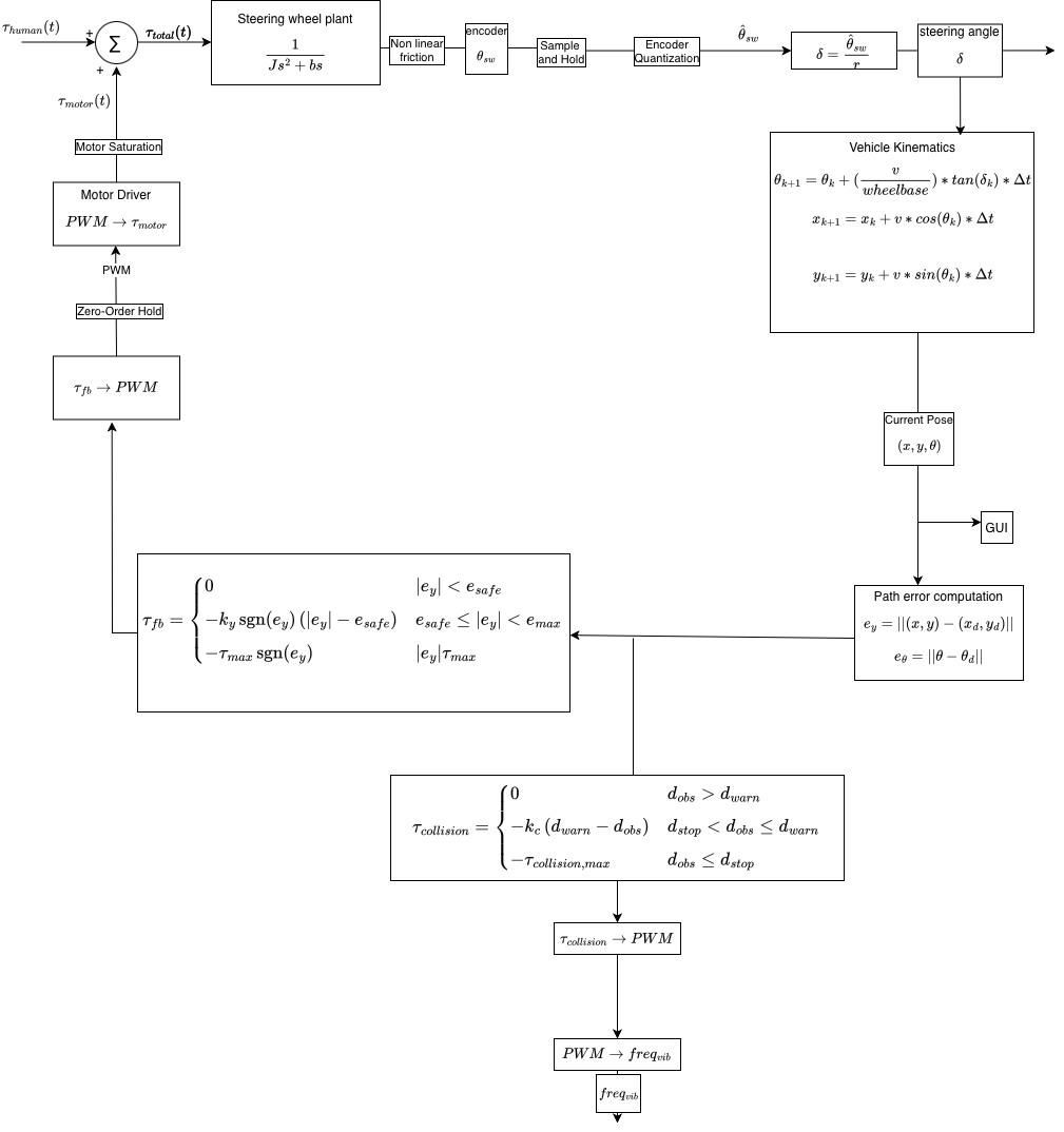
To better represent the physical system, several nonlinear and discrete-time effects were incorporated into the model.
Position Sensor Quantization
The encoder measures steering angle with finite resolution,
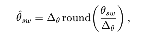
where delta-theta is the encoder step size. This introduces a small quantization error in the measured steering angle.
Sample-and-Hold
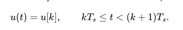
The steering angle is sampled every Ts seconds,

As a result, the measured position remains constant between sampling instants.
Zero-Order Hold
The controller output is updated discretely and held constant between updates,
This produces a piecewise-constant motor command.
Nonlinear Friction
The steering wheel damping is modeled as velocity-dependent,
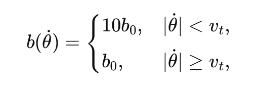
with friction torque,
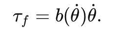
This approximates the increased resistance observed at low steering velocities.
Actuator Saturation
Motor torque is limited by the actuator's physical capabilities,
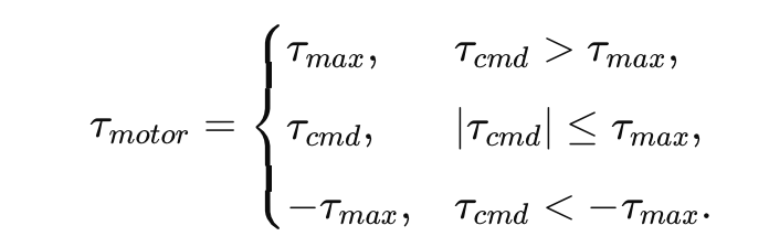
This prevents unrealistically large torque outputs and enforces actuator limits.
Demonstration / Application
The final system demonstrated a physical haptic interface for a virtual parallel-parking task. The user sat in front of the computer and controlled the car in Processing by turning the physical steering wheel. The simulation displayed the road, parked cars, parking space, oncoming traffic, and the user�s car in real time. The demonstration showed that the system could combine physical steering input, real-time graphics, and haptic feedback into one interactive simulator. When the user successfully parked, the car stopped inside the green parking space and the game was sent back to IDLE mode. This confirmed that the hardware and software were communicating correctly and that the simulator could detect task completion.
This system could be applied to driver education, rehabilitation, or other training environments where users need to learn a motor skill safely before performing it in real life. A similar haptic simulator could also be expanded to teach other driving tasks, such as backing into a parking spot, avoiding obstacles, or practicing steering control in low-speed maneuvers. The project shows how haptic feedback can make a virtual training environment more interactive and intuitive by allowing the user to both see and feel the effects of their actions.
Results
The parallel parking simulator accomplished the objectives outlined in our Project Proposal. During the Training Round, the DC motor controlled the steering wheel, guiding the vehicle through an ideal parallel parking maneuver while the user maintained light contact with the wheel. In the Game round, both the DC motor�s kick and the vibration motors� vibrations began during collision with either the top or bottom cars, and the motion of the wheel was correctly tracked and transformed into motion of the car using the 15:1 driving ratio. The user could continue to do the Training or Game rounds repeatedly by selecting the corresponding button.
Attached below are videos of (1) a user during the Training Round, (2) a user during the Game round parking the car with no collisions, and (3) a user experiencing haptic feedback during a collision with the adjacent parked car.
Since the vibration motors are hard to see/hear, below is another video that shows the vibration motors spinning while detached from the steering wheel.
Collision, showing vibration motors
To assess the effectiveness of our simulation, we conducted an anonymous Google Survey during our demonstration. Participants first experienced the Training Round, followed by the Game Level, and were asked to answer the following questions regarding their experience, with an option to leave additional comments. There were 19 total participants.
1. How good was the simulation's haptic feedback? (1-5)
- Response: the average response score of all respondents was 4.95, with the lowest score given being a 4 and the highest score given being a 5.
- Reflection: the guided feedback was well-received, and people responded positively to the combination of the "kick" motor feedback and vibration feedback during collisions with other cars.
2. Rate the realism of the simulation on a scale of 1-5.
- Response: the average response score of all respondents was 4.58, with the lowest score given being a 3 and the highest score given being a 5.
- Reflection: realism scored relatively highly, demonstrating that the 15:1 driving ratio from steering wheel to simulation was well received and made the simulation feel similar to driving a car. Other aspects of the simulation could be made more realistic, such as not allowing users to continue colliding with cars. These changes would require a more powerful motor to more strongly veer the user during collisions.
3. Rate the stability of the system. (1-5)
- Response: the average response score of all respondents was 4.89, with the lowest score given being a 4 and the highest score given being a 5.
- Reflection: the stability also scored highly, demonstrating that the k values we chose were well calibrated and the vibrations were set to a PWM that was obvious but not overpowering. Further improvements, such as adding more damping throughout gameplay, may improve stability even further.
4. Rate the graphics of the simulation. (1-5)
- Response: the average response score of all respondents was 4.74, with the lowest score given being a 4 and the highest score given being a 5.
- Reflection: graphics scored relatively highly, but the five "4" ratings suggest that further enhancement could improve the simulation in the future. Adding a driver-view perspective rather than only a top-down view is one potential enhancement, along with adding more on-screen cues during collisions.
Overall, the poll�s results demonstrate that participants felt that our simulation was an effective parallel parking simulator, with good realism, stability, graphics design, and haptic feedback.
Future Work
Our system could be tested by users using the steering sequence (via calculated steering angles) while parking an actual parked car. Our system could be improved by providing strong haptic feedback after hitting the cars in the game mode, and really jerking similar to a real collision. This could be done using a stronger motor and implementing a capstan drive. Furthermore, we could provide more granular vibration feedback to give the user more queues about which direction they need to adjust to and how close they are to a collision. This could be implemented with a �warning zone� around the actual collision zone, and programming the vibration motors independently instead of together.
Files
References
A. Balachandran, M. Brown, S. M. Erlien and J. C. Gerdes, "Creating predictive haptic feedback for obstacle avoidance using a model predictive control (MPC) framework," 2015 IEEE Intelligent Vehicles Symposium (IV), Seoul, Korea (South), 2015, pp. 31-36, doi: 10.1109/IVS.2015.7225658.
Ciara J. Murphy, Adam J. Toth, Fazilat Hojaji, Mark J. Campbell, Force feedback drives sim racing performance: The influence of force and vibrotactile haptic feedback in simulator steering wheels, Computers in Human Behavior Reports, Volume 22, 2026, 100993, ISSN 2451-9588, https://doi.org/10.1016/j.chbr.2026.100993.
S. M. Petermeijer, D. A. Abbink, M. Mulder and J. C. F. de Winter, "The Effect of Haptic Support Systems on Driver Performance: A Literature Survey," in IEEE Transactions on Haptics, vol. 8, no. 4, pp. 467-479, 1 Oct.-Dec. 2015, doi: 10.1109/TOH.2015.2437871.
Appendix: Project Checkpoints
Checkpoint 1
For checkpoint 1 we had 4 main goals and they were as follows:
- Create a basic/rough draft of GUI
- Create a block diagram for controls analysis
- Determine our equations of motion for vehicle turning
- Implement vibration feedback for collisions
For goal 1, we met all our expectations and completed a first rough draft of the GUI. We completed the GUI using processing. It has a 1-lane road with oncoming traffic and the user is to park the red car in the green parking spot with no collisions.
See photo below for GUI.
For goal 2, we met all our expectations and completed a block diagram for the controls analysis. This block diagram is still a work in progress as we fine-tune the controls aspect of our project, but it gives us a good start.
See photo below for block diagram.
We also did a more in depth outline of how our system will run. Below is the overview. One of our key analysis will be developing the kinematic trajectory for a nominal parallel park, which, during the training level, will be the path which the car follows.
1. Project Goal and Nominal Path Definition
The goal is to develop a parallel parking simulator with haptic feedback.
- Nominal Kinematic Path: The desired trajectory for a perfect parallel park will be calculated.
- Corridor: A corridor will be applied around the nominal path to provide the user with flexibility in steering, allowing them to recover from initial errors.
2. Car State and Kinematics
The state of the car is calculated based on constant reverse velocity (v) and steering angle (δ) (from the wheel).
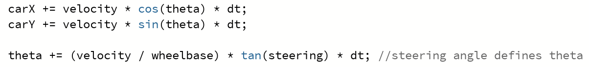
Kinematic Update
At each timestep (Δt):
x_k+1 = x_k + v cos(θ_k) Δt
y_k+1 = y_k + v sin(θ_k) Δt
θ_k+1 = θ_k + (v/L) tan(δ_k) Δt (where L is wheelbase)
System Steps
At each step, our system will perform the following sequence:
- Read encoder
- Propagate state
- Find nearest path point
- Compute errors
- Compute torque
- Send PWM
3. Ground Truth and Error Calculation
Ground Truth Data
The nominal parking path information will be collected using computer vision from a top-down video of a perfect parallel park.
Alternatively, the nominal path can be modeled using two circular arcs (one right, one left):
| Segment | Steering |
|---|---|
| Reverse straight | 0° |
| Enter spot | Max right |
| Rotate vehicle | Hold |
| Countersteer | Max left |
| Align | Straighten |
Error Definitions
After calculating the closest point projection, the system computes the following errors, which are used as the restoring force:
- Lateral Error (E_y): Distance to path
- Heading Error (E_θ): θ - θ_d (Current Heading - Desired Heading)
4. Haptic Feedback (Torque Output)
The haptic feedback provides a restoring force (τ) and follows the virtual corridor logic.
General Haptic Torque Formula
The haptic torque (τ) output is calculated using a feedback law:
τ = -k_y*E_y - k_θ*E_θ - b * dot(δ)
Piecewise Haptic Function (Lateral Error)
This is considered the cleanest first implementation.
- e_y: Lateral error
- e_safe: Warning threshold
- e_max: Hard limit
The feedback torque (τ_fb) is defined as:
τ_fb = {
0 if |e_y| < e_safe;
k1(|e_y| - e_safe) if e_safe ≤ |e_y| < e_max;
τ_max sgn(e_y) if |e_y| ≥ e_max
}
Collision Avoidance
Collision avoidance is provided as a vibration output only when the car is about to hit something.
For goal 3, we came up with our equations of motion by modeling the car off of a bike. We ultimately decided to model the car off of a bike because it dramatically simplifies the dynamic equations compared to modeling off of 4 wheels. The wheelbase is the distance between the front and rear wheel axis, steering is the steering wheel angle (from the arduino), and theta is the angle of the car.
Our equations of motion are as follows:
For goal 4, we used our hapkit board and 2 vibration motors to implement collisions. We initially had a hard time getting our vibration motors to turn on. We connected the vibration motor to a transistor and had problems debugging our circuit. Eventually, we got it and our vibration motors turned on. Eventually we got them working and turns out our transistor was just backwards.
Checkpoint 2
For checkpoint 2 we had 4 main goals. They were as follows:
- More complete graphical interface showing 2 parked �cars� and the gap in which the user should try and park
- Fine-tuned vehicle dynamics � implement equations of motion from Checkpoint 1
- Steering wheel printed and connected to motor
- Implement force feedback to guide user on correct trajectory
For goal 1, we had already met it in checkpoint 1. So we kept our GUI the same since we were happy with how it's looking. Please refer to checkpoint 1 for an image of the GUI.
For goal 2, to fine-tune dynamics we added a 1:15 ratio for steering wheel to car movement. This is to simulate how an actual car drives. We also integrated the data communication between Arduino and processing. We also adjusted the theta so that it actually simulates driving and it has a constraint of -60deg to 60deg rotation (like a real steering wheel).
For goal 3, we made a 3D model of a steering wheel and printed it out of PLA. We attached the steering wheel directly to the motor. We will plan to add a capstan drive if we need more motor torque, but for now direct drive has been working. We have also been working on a motor stand model, but for now we're using a kombucha bottle and lots of tape.

For goal 4, we had started a lot of code last checkpoint, but hadn't tested any of it. We started implementing the code in chunks by first just getting the car to move in processing. We knew implementation would be the hardest and we spent a lot of time debugging. We wanted to implement the training round for our project which should guide the user into the parking spot. Our biggest issue was a buzzing sound when applying a force to the motor. We improved the buzzing issue by changing the PWM frequency since the PWM frequency at default is in the audible range. We still have some buzzing issues due to the timing not being consistent.
Challenges and Milestones
One of our big challenges and milestones this week was accurately getting the angle readings. We were originally using the encoder's analog function, but that did not use the I2C, so in order to get absolute angle readings, we switched over to using I2C and the SDA, SCL, and PWM pins on the encoder. We also had an issue where the car was turning in only one direction and would start spinning rapidly for certain angles. We figured out that this was because we were using tan(theta) in one of our calculations, and this was becoming undefined. We constrained the angle to stop this from occurring. We also had a cos(theta) that was making our left turn angles negative, and so constraining the angle between 60 degrees and -60 degrees fixed this.
For our haptic feedback with the motor, the free wall in the "training" simulation was having issues with providing enough torque because the motor was not getting enough current from the hapkit board, so it only reacted to the wall when there was no load (when we weren't holding the wheel). We want a strong resistive force to guide the user, so until we can get the right electronics for the original motor, we switched over to the hapkit's motor which provides enough resistive force for us to test our code and simulation's functionality. You can see in the video below the parameters are able to guide the hapkit to park the car in the parking spot.
Current Problem Another issue we are encountering is timing. The motor pins of the Hapkit board are connected to Timer 0, and Timer 0 is also used for millis() and timing Arduino functions. We looked into previous assignments and saw that each loop was counted as a 1 ms estimate. We tried doing this as well, but because we are using events and a state machine, our loops are not equal time. We need timing for our velocity calculations, and are not sure how we can read timing with the current board.