

2026-Group 5
Haptic Enhancement of Palpation via viBrotactile feedback
Project team members: Yuxuan Wu, Wentao Ke, Billy Gao & Jeffrey Cai
On this page... (hide)
Introduction
Haptic perception is an essential component of many medical procedures. General surgeons and other medical practitioners rely heavily, both consciously and unconsciously, on tactile information when palpating tissue, manipulating instruments, and performing surgical tasks. While visual feedback is often the dominant information mode in medical environments, haptic feedback provides complementary information that is difficult to obtain visually, such as stiffness, depth, and internal structural variations.
We propose to develop a haptic medical device that enhances a user�s ability to perceive subsurface targets during palpation examinations through vibrational feedback. The goal of this project is to improve the detectability of targets that are difficult or impossible to palpate directly, thereby providing users with a better understanding of target location and depth within soft tissue. More specifically, we aim to achieve a form of �hyper-realism� in haptic rendering, where non-palpable targets can become perceptually palpable through augmented feedback. By augmenting tactile perception, our system has the potential to improve target localization and enhance the effectiveness of palpation-based examinations.
Background
Prior work shows that the character of haptic feedback, not just its presence, drives target localization. Sch�tz et al. for instance used shape-based sonification to help surgeons localize tumor boundaries. Their method changes the audio profile based on whether the sensor is over the seed, tumor, or healthy tissue, and users prefer it. We can leverage this changing-stimulus idea at the tumor boundary, with a slow pulsation that turns into a rapid, strong vibration over the tumor.
Abiri et al. evaluated a normal-force and vibrotactile system for palpation, where bimodal vibrotactile feedback significantly outperformed no-feedback and force-only conditions when localizing hidden vessels and tumor-like structures. This validates triggering a vibration motor once force sensing exceeds a defined threshold to direct user attention.
Niwa et al. fed fingertip skin vibrations back to the temples to enhance perception during contracture palpation, lowering detection thresholds significantly. An implication is to relocate the ERM off the palpating hand to avoid a feedback loop that interferes with natural touch.
Methods
Hardware Design and Implementation
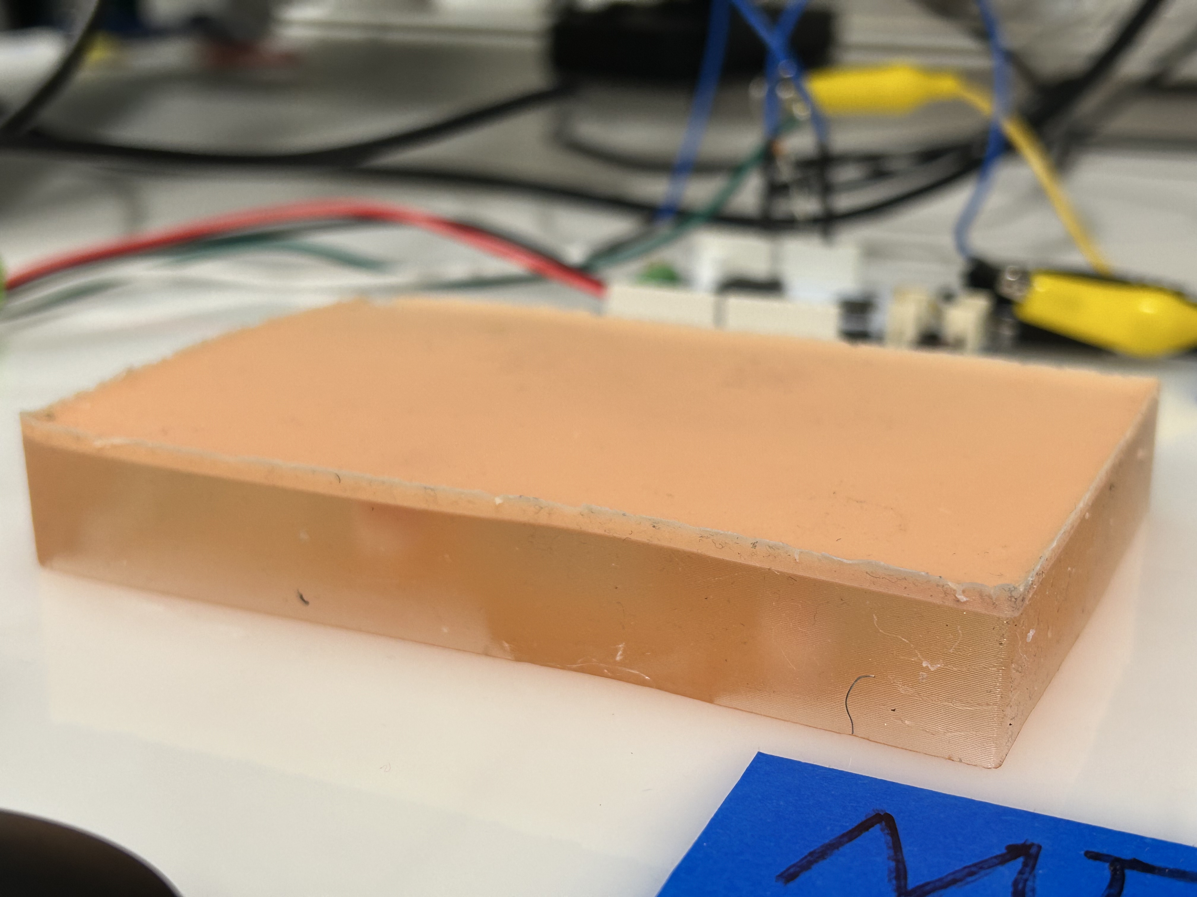
Phantom Preparation
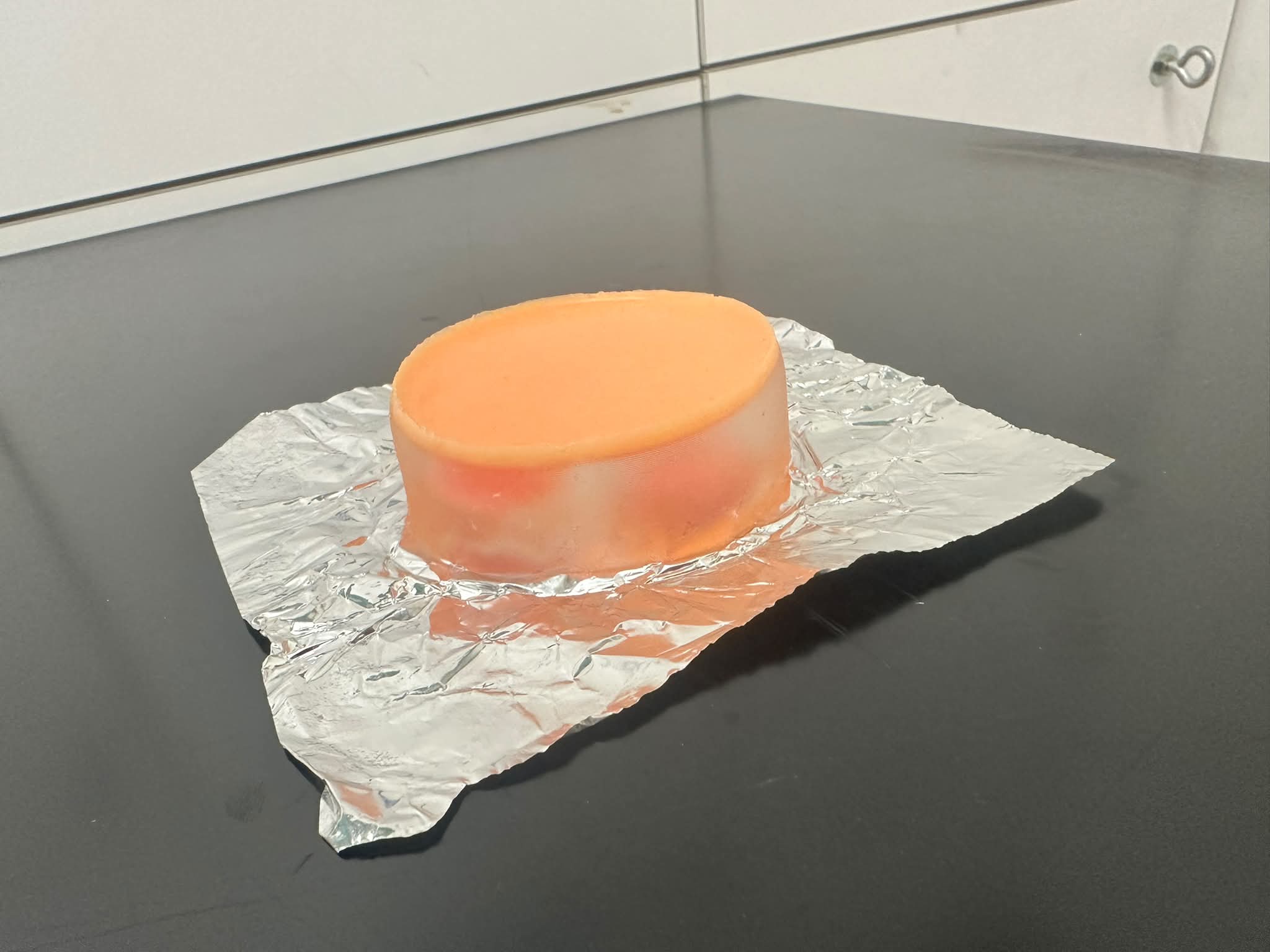
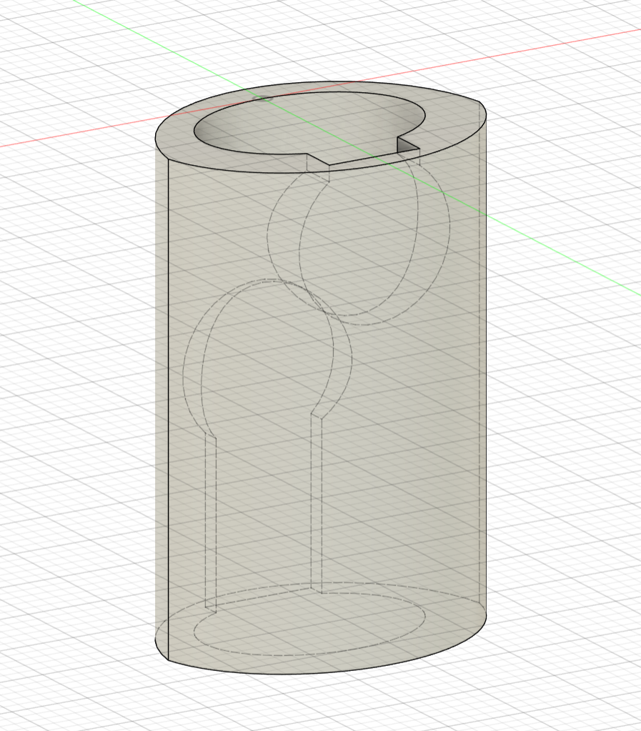
To evaluate the vibrotactile feedback system, a custom soft tissue phantom was fabricated to simulate the mechanical contrast between compliant healthy tissue (Smooth-On Ecoflex� Gel) and stiffer malignant tumors (Smooth-On Ecoflex� 00-50). To test the system�s ability to render varying sizes at a constant depth, four tumors were cast using custom 3D-printed molds with specific geometries: two large 10 mm radius semi-spheres and two small 5 mm radius full spheres. Because both designs share an identical Z-axis height of 10 mm, resting them on the same horizontal plane guarantees that their top surfaces sit at an identical depth beneath the phantom's surface, effectively isolating size as the primary variable.
The main phantom body was constructed in an 8 cm * 12 cm 3D-printed rectangular mold using a two-layer casting process to embed the tumors at varying depths. First, one large and one small tumor were sparsely distributed at the bottom of the mold before pouring the initial layer of Ecoflex Gel. Once partially cured, the remaining two tumors were placed on top of this base layer, and the mold was filled completely. Because the tumors were positioned loosely rather than fixed to a grid, their exact X and Y spatial coordinates were manually measured post-curing. These precise locations were then programmed into the software�s spatial map to calibrate the hand-tracking system and synchronize the ERM actuators with the physical inclusions.
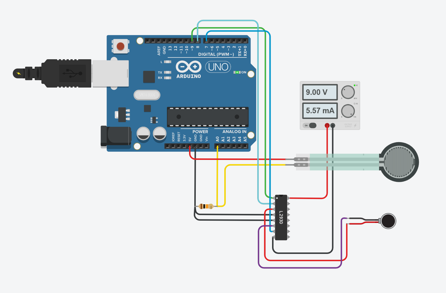
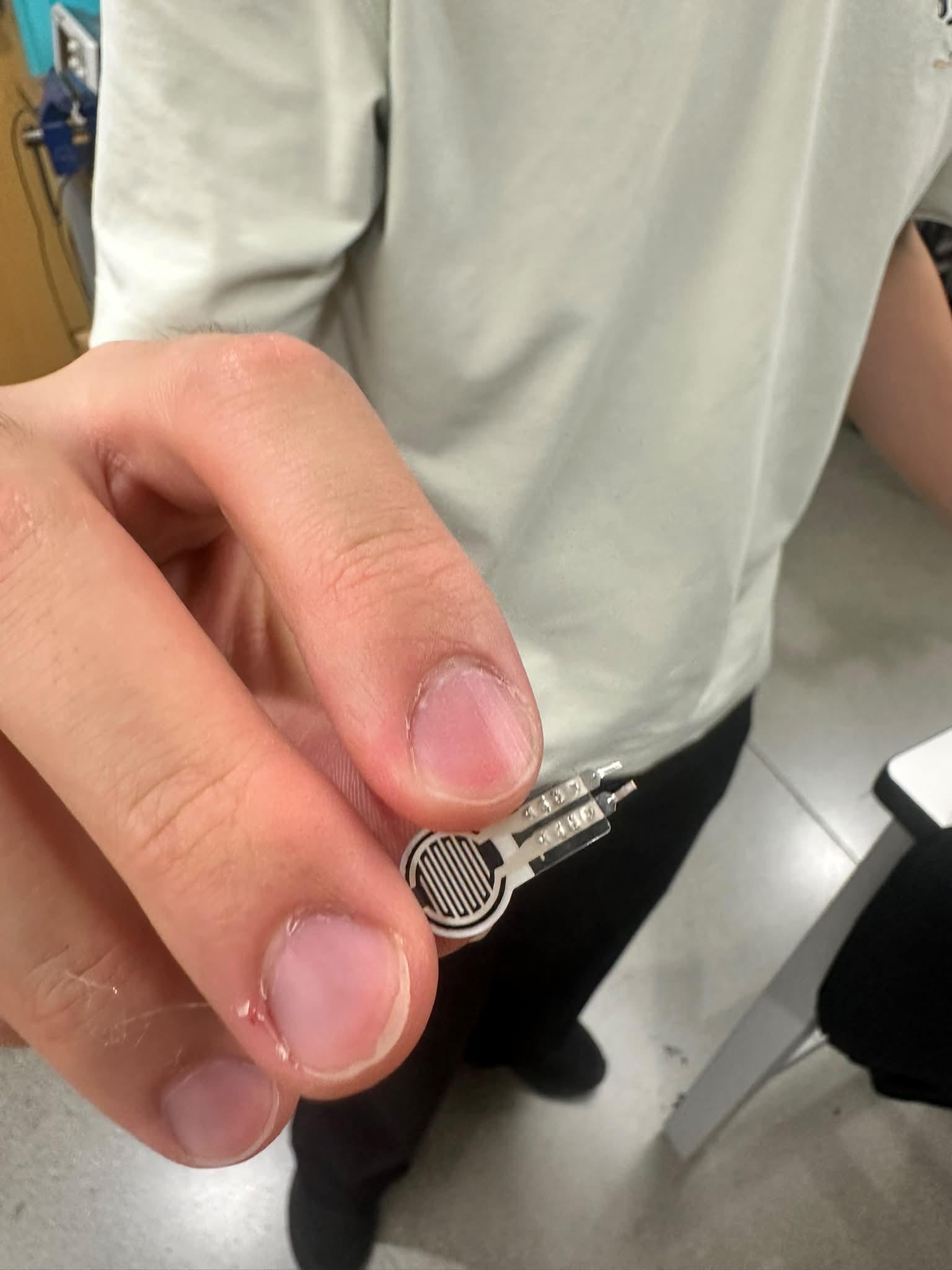
Force Sensing
To accomplish force sensing, we used the Hapkit Arduino board to form a simple voltage divider setup with the force-sensitive resistor (FSR). In this setup, a large resistance value (e.g. 1MΩ) makes the analog reading more sensitive towards lighter touches, since the order of magnitude of the FSR resistance is close to that when untouched. On the other hand, small resistance values (e.g. 1kΩ) allow for better sensitivity towards heavy pressure. Since our design goal was to discriminate between light-medium pressure and high pressure, we used a middle resistor value of 10kΩ to resolve a good sensitivity in the transitional zone between a light and heavy touch.
The circuit diagram ported to TinkerCAD is as follows (note that on the Hapkit board, the motor driver is built-in):
Link via TinkerCAD: https://www.tinkercad.com/things/00omlRoV2Wv-me327-simple-fsr-erm-setup?sharecode=W2ReFPdJAFp_Fp1CJ3O27JLYWWcC7aliQsV5mE5tSLA
Vibrational Feedback
To deliver vibrational feedback to the user, we used one ERM locally fixed to the fingertip, near where the FSR is attached. The ERM was driven both via pulse-interval modulation and constant amplitude-driven vibration, based on whether the user�s position was outside the tumor zone or inside it, respectively. To maintain a comfortable vibrational strength for the user, we made the continuous strength have a PWM value of 30 and 50 for weak and strong vibrations respectively. For the pulse-interval modulation mode, we used a variation from 30 to 60 (all out of 255).
We chose to use a single ERM because it best balanced the tradeoff between form factor and sufficiently understandable feedback. When we tried to attach two ERMs to the same finger, users who tested the device indicated that they only felt a single vibration. To make it more useful, we could have had to attach two ERMS on different fingers. However, that runs contrary to one of our objectives, which is making the device minimally cumbersome and easy to use. Attaching components on opposite sides of the hand would require a glove-like device that covered a large portion of the hand. Not only would this make it difficult for a vision-based algorithm to recognize the hand, it would also make it less practical to use in real palpation scenarios because it would interfere with the examiner�s dexterity. Therefore, using two ERMs by varying the strengths of vibration was not a fruitful endeavor.
Software Design and Implementation
Hand Tracking and Phantom Calibration
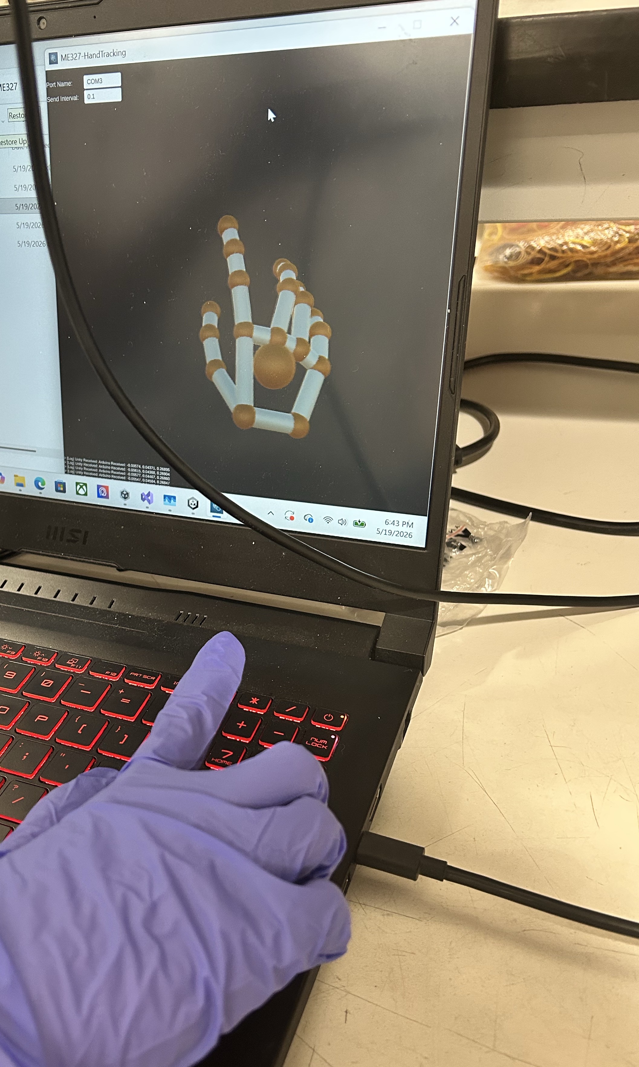
We used an Ultraleap Leap Motion Controller 2 for hand tracking. A custom Unity application was developed to visualize the hand skeleton and transmit the tracked index fingertip position to an Arduino via a serial connection.
To determine the pose of the phantom relative to the hand-tracking camera, the user is instructed to touch the four corners of the phantom while the corresponding fingertip positions are recorded. These recorded points are then matched to the known corner locations of the phantom, and a rigid registration algorithm is used to compute the phantom's pose. The tracked fingertip positions are subsequently transformed into the phantom's coordinate system before being sent to the Arduino.
Haptic Rendering Algorithm
The Arduino then determines the vibration mode and intensity based on the fingertip position relative to the known tumor locations, as well as each tumor's size and depth. When the fingertip is outside the boundary of all tumors, the ERM motor operates in a periodic pulsing mode. The pulse intensity increases as the fingertip approaches a tumor, providing a proximity cue to guide exploration.
Once the fingertip enters the radius of a tumor, the ERM motor switches to a continuous vibration mode. In this mode, the vibration intensity is determined by the force applied by the user, as measured by the FSR. For a shallow tumor, successful palpation requires the applied force to fall within a prescribed range, where the FSR value must be greater than the minimum shallow threshold and less than the maximum shallow threshold. For a deep tumor, a larger force is required, and the FSR value must exceed the minimum deep threshold.
These force thresholds emulate the different palpation pressures required to detect tumors located at different depths within soft tissue, while the pulsing vibration outside the tumor region provides spatial guidance to help users locate the tumors.
System Analysis and Control
PIM Guidance
The system couples a Unity position tracker to an Arduino driving a single ERM motor based on finger location and applied pressure. Unity streams probe position, the ERM is driven by PWM, and an FSR is read. Tumors are stored as an (x, y) center, radius, and shallow/deep flag. Control runs as two layered behaviors.
For localization, the code computes the in-plane distance from the current position to the nearest selected tumor's edge and maps it to intensity. The intensity is zero beyond 4 cm with a linear ramp from a PWM floor up to a ceiling as the user approaches, and full intensity once inside the tumor footprint. Outside the tumor the motor pulses at the distance-scaled intensity to signal and inside the tumor it switches to continuous vibration.
For depth discrimination, once inside a tumor we check the FSR reading against pressure windows, pressure in the range matching to the depth of the tumor produces strong continuous vibration and not matching pressure produces weak continuous vibration.
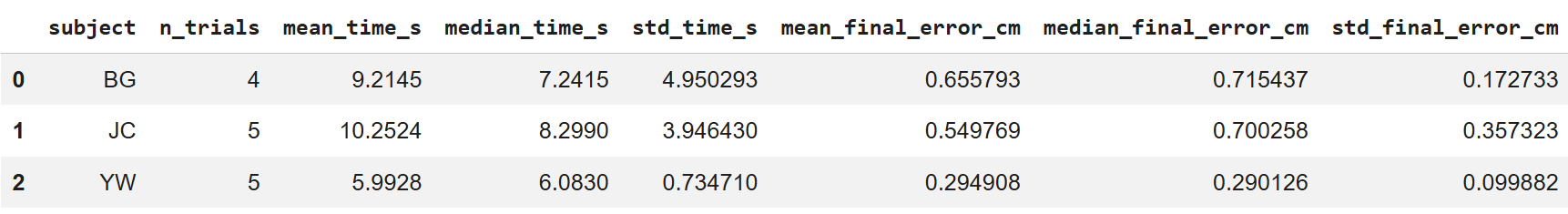
To analyze whether our feedback modality is effective at the task of compelling users to move towards the tumor, we conducted a user study to see how long it would take to localize the position of an unknown tumor. To do this, we randomly generated a setpoint in the phantom tissue�s dimensions. The user then has to use the vibrational feedback to locate the generated location and press down to confirm they�ve found it. This was repeated for several trials per user.
The resulting graphs plot the results of the study. The three users all had a median exploration time of 10 seconds or lower. The error at the end of each trial was, on average, less than 1 cm. Users agreed that the mode-switching from the PIM actuation mode to the continuous mode was what indicated to them that they were on top of the tumor.
Different users also exhibited different strategies for exploration. BG pressed down to confirm the location of the tumor immediately when they reached the setpoint. JC bounced back and forth to confirm that they were really feeling the tumor.
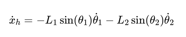
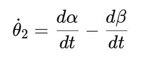
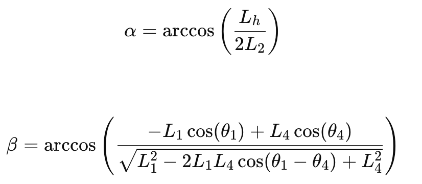
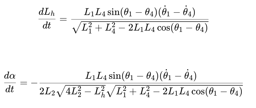
Finger-Tissue Contact Model
We model the contact of the user�s finger with the tissue as three compliant materials in series, which gives the following relationships for displacement and force.
Here, f corresponds to fingertip, h to healthy tissue, and t for tumor tissue. The equivalent stiffness for compliant materials in series is therefore:
For the sake of simplicity, we neglect the non-linear and viscoelastic effects to get a rough sense of the ratio of required user force for shallow palpations (small deformations).
Physical Parameters for Contact Model
For our system, we casted the tumor tissue out of Ecoflex 00-50. The spec sheet reports the 100% modulus of the material as 12 psi, or 82.7 kPa. The healthy tissue was cast out of Ecoflex GEL, which is much softer than the tumor region. An estimate used by Lee et. al. is 20 kPa. Oprişan et al. models the human finger stiffness as a range from 0.07 MPa to 0.20 MPa, so we can take roughly 100 kPa as a middle value.
Maiti et. al. reports the finger pad contact area as ranging from 75 mm2 to 160 mm2 as the force applied ranges from 0.5 to 3 N. We use 100 mm2 as a round estimate for our calculations.
As for effective compression depth into the phantom tissue, we chose a value of 10 mm. For the tumor tissue, we modeled it as roughly 5 mm of healthy tissue followed by 5 mm of tumor. This is a compression that is characteristic of palpating the shallow tumors, but more importantly it is chosen for the sake of analysis so that we can still roughly estimate the interaction as very roughly linear elastic for small compressions. Compression depth into the human fingerpad is roughly given by Serhat et. al. as 5 mm.
Combining this, calculating the stiffness gives the following values for fingertip (f), healthy (h) and tumor (t).
The stiffness ratio between tumor and healthy tissue is 1.53. Although it is a rough estimate, it shows that the difference in force needed to compress the healthy vs. tumor regions are not extremely disparate. This calculation is also only modeling the shallow tumor. For the deep tumor, the difference in force would be even harder to detect, which justifies the use of our vibrotactile feedback system.
FSR Reading
When the user contacts the phantom through the FSR, we get a reading of the user�s force, which needs to be normalized and clamped so that it can be used to inform the ERM vibrational strength.
ERM Vibration
For an eccentric rotating mass motor, the off-axis mass exerts a force that relates to its angular velocity via
The important takeaway from this is that using a PWM signal to drive the ERM would scale the angular velocity linearly with the PWM signal. Therefore, the force applied by the ERM would scale quadratically with PWM signal strength.
If we wanted to make the perceived vibrational strength roughly scale evenly as force increases, we could use a square root mapping (although in our real device we found a discrete jump was easier to observe).
A characteristic mass for the eccentric motor is ~0.2 g, and re is around 1mm.
Overall Block Diagram
Results
Demonstration / Application
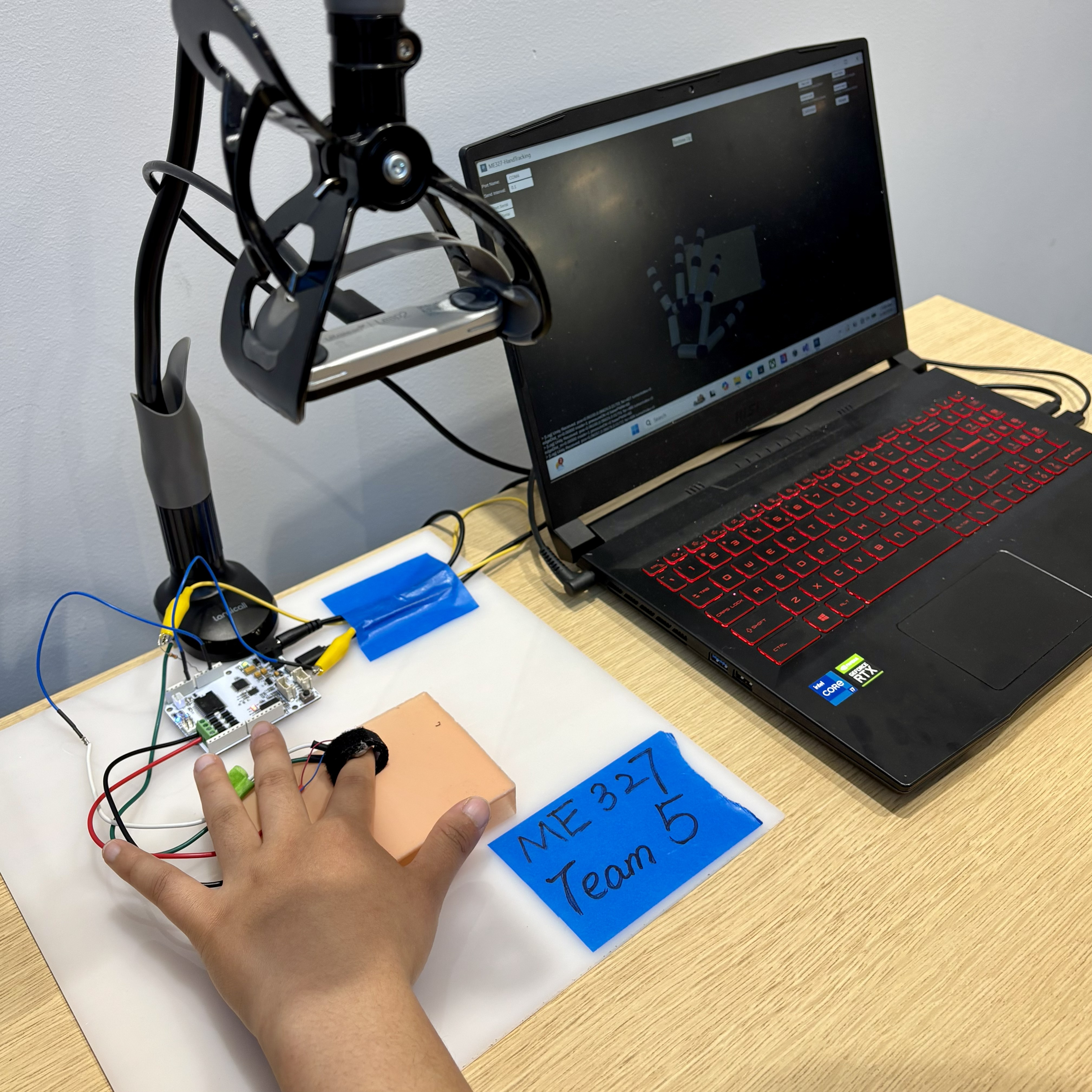
System setup during operation. The hand-tracking camera is mounted on a phone holder and positioned above the phantom to provide a top-down view. The user wears a Velcro ring with an FSR mounted on the fingertip side and an ERM motor mounted on the dorsal side, both connected to an Arduino. The Arduino communicates with a computer running the hand-tracking software. The user interface visualizes the tracked hand skeleton and the phantom model in real time.
At our open house, users wore the haptic feedback ring and located tumors embedded under the phantom tissue substantially faster than with the baseline condition. The ring guided testers to the correct position by increasing feedback as they swept over the tumor zone, and most found this localization step compelling and a clear improvement over the status quo. Testers also reported a noticeable change in vibrational mode when they pressed down on a tumor through the silicone phantom, which encoded the depth of the tumor. This depth cue was less salient than the localization feedback, but users still registered it.
Quantitatively, most testers rated the noticeability of the feedback as 5 out of 5, and rated the functional improvement over the baseline between 4 and 5. The main critique was that wearing the device on the finger prevents the user from directly feeling the tumor with their own fingertip, which points to relocating the actuator off the palpating finger in future iterations.
Future Work
While the current system successfully demonstrates the viability of utilizing vibrotactile feedback via ERMs to communicate tumor depth and size based on a pre-calibrated spatial map, clinical applications require a system capable of real-time, autonomous localization. Currently, the FSRs function primarily as user-input triggers, relying on an external hand-tracking system and known tumor coordinates. Future iterations should shift the paradigm from rendering known virtual maps to actively sensing unknown physical environments.
To achieve this, our future work will focus on the following engineering advancements:
1. Integration of High-Resolution Tactile Senor Arrays: In the real world, the exact location of a tumor is unknown, meaning the clinicians must rely on the physical deformation of the patient�s tissue to detect abnormalities. Future prototypes should replace single-point FSRs with distributed tactile sensor arrays, which will measure not just bulk normal force, but localized pressure gradients and tissue deformation profiles.
2. Real-Time Tissue Stiffness Estimation & Closed-Loop Haptic Rendering: Real-time data processing algorithms that combine kinematic data(finger position and velocity) with tactile data(contact force and tissue replacement) should be implemented. Then the sensory data acquired from tissue deformation will directly and dynamically scale the ERM. By calculating the dynamic stiffness such as localized Young�s modulus, the system should be able to tell the difference between healthy tissue and stiffer nodules and provide different haptic feedback for the users.
3. Testing on Heterogeneous Ex-Vivo Phantoms: Instead of homogenous phantoms, multi-layer, heterogeneous tissue phantoms that accurately mimic the varying compliances of human skin, fat, and muscle should be utilized. This will pave the way for ex-vivo animal tissue testing, ensuring the sensors and rendering algorithms are robust enough to handle the non-linear, viscoelasticity properties of real biological tissues.
Files
References
Sch�tz, L., et al. (2024). Interactive Shape Sonification for Tumor Localization in Breast Cancer Surgery. CHI '24. https://doi.org/10.1145/3613904.3642257
Abiri, A., et al. (2019). Artificial palpation in robotic surgery using haptic feedback. Surgical Endoscopy, 33(4), 1252�1259. https://doi.org/10.1007/s00464-018-6405-8
Niwa, K., et al. (2021). Vibrotactile Feedback System From the Fingertip to the Temples for Perceptual Enhancement of Contracture Palpation. IEEE Transactions on Haptics, 14(2), 285�290. https://doi.org/10.1109/TOH.2021.3074174
Lee, S., et al. (2026). �Deformation Driven Suction Cups: A Mechanics-Based Approach to Wearable Electronics.� Advanced Science13, no. 20 (2026): e20417. https://doi.org/10.1002/advs.202520417
Oprişan, C., et al. (2016). Experimental determination of the Young�s modulus for the fingers with application in prehension systems for small cylindrical objects. IOP Conference Series: Materials Science and Engineering, 147, 012058. https://doi.org/10.1088/1757-899X/147/1/012058
Maiti, R., et al. (2026). "Quantification of the Real Contact Area of a Finger-Pad During Sliding Using a Novel Optical Coherence Tomography System and the Influence of Skin Thickness." ASME. J. Tribol. May 2026; 148(5). https://doi.org/10.1115/1.4070952
Serhat, G., & Kuchenbecker, K. J. (2021). Free and Forced Vibration Modes of the Human Fingertip. Applied Sciences, 11(12), 5709. https://doi.org/10.3390/app11125709
Smooth-On. (n.d.). Ecoflex Gel Technical Bulletin. https://www.smooth-on.com/tb/files/ECOFLEX_GEL_TB.pdf
Smooth-On. (n.d.). Ecoflex Series Technical Bulletin. https://www.smooth-on.com/tb/files/ECOFLEX_SERIES_TB.pdf
Appendix: Project Checkpoints
Checkpoint 1
From the project proposal, the checkpoint goals that we have so far are as follows:
- Order materials: FSR
- Create CAD models for the molds that will be used for silicone phantoms, and potentially 3D print them
- Complete the paper presentation
- Test whether the hand tracking can identify the hand and its position with the ERMs mounted
The goal of ordering FSRs has been met: this is one of them.
We have also successfully prepared the silicone phantoms that will be used.
The paper presentation might or might not happen this week. The hand tracking has been tested, with successful communication between Unity and Arduino using SerialPort.
The current bottleneck that we are facing is regarding the mounting of the FSRs and the ERMs. We realized that it may be difficult to simultaneously mount the FSR and ERM on top of fingers since it would be a really small area and the existence of the FSR may affect the ERM. A potential deviation to solve this problem is by CADing and making a elastomeric ring made of silicone, which could attach the FSR to the front of the finger and the ERM to the back of the finger.
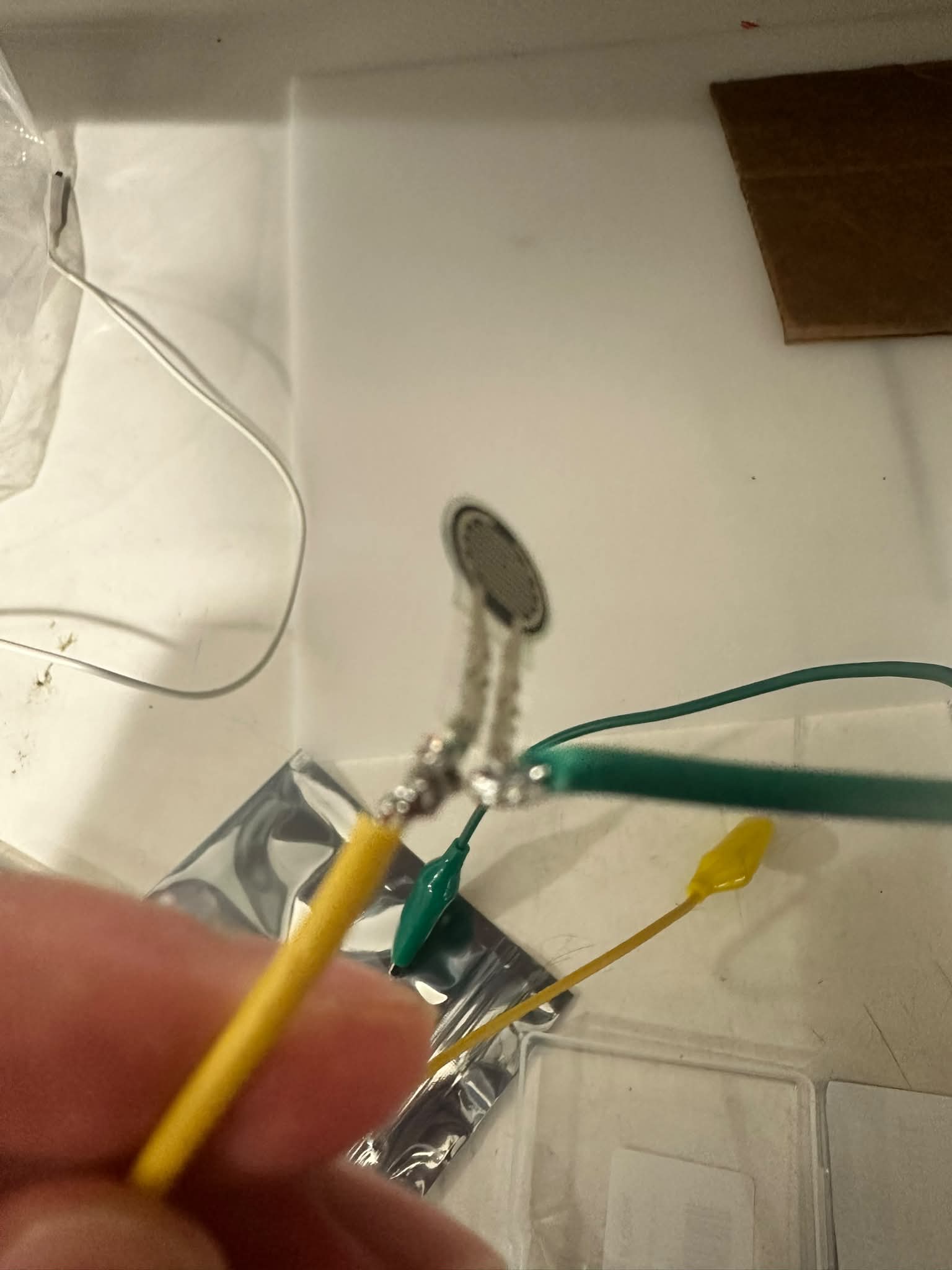
Another unexpected challenge is how to connect the FSRs to power. The solution that we have found is by attaching a soldering iron to the wire and FSR connection.
Checkpoint 2
From the project proposal, the checkpoint goals that we have for this week is as follows:
- Fuse FSR with the ERM by implementing Arduino code to output different vibrational levels based on pressure applied
- Complete and improve hand tracking interface
- Test different vibrational modes for the ERM
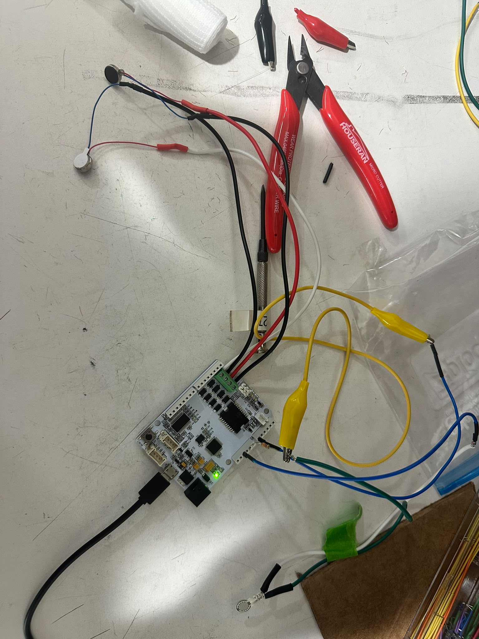
For the FSRs, we connected them with the Arduino's 5V and GND using a 10k resistor to form a simple voltage divider setup. We obtain signal from an analog input pin. To allow for two connections with our single 5V pin without using an external breadboard, we soldered together a forked jumper wire.
From there, we can read the FSR signal, which we threshold into different strength levels to categorize no touch, light touch, and heavy touch.
The ERMs are then connected and to the Arduino by soldering the leads onto stranded wire as well. We tested different strength of vibration correlating to FSR signal strength. For legibility, we used color coded heat shrink and wiring to keep track of which wires are which.

The hand tracking interface has also been built and can be more intuitively accessed from the user interface. We also compiled it down to an executable so it wouldn't have to run in Unity.
The current bottleneck and challenge is that to put the entire thing together both physically and software wise. Physically it is mainly regarding how to mount it on the users' hands. For instance, the power supply, the glove, the erm, Arduino and FSR placements. From the software side, it is to use the hand tracking system to inform the existing Arduino FSR + ERM setup on whether or not the user's index finger is over a specified tumor area.
The final part of our integration is calibrating how strong the vibration should be and which type of vibrational signal we should use to signal each circumstance (e.g. inside the tumor region or not). That should also combine with a varying level of vibration corresponding to strong/weak pressure.