

2026-Group 7
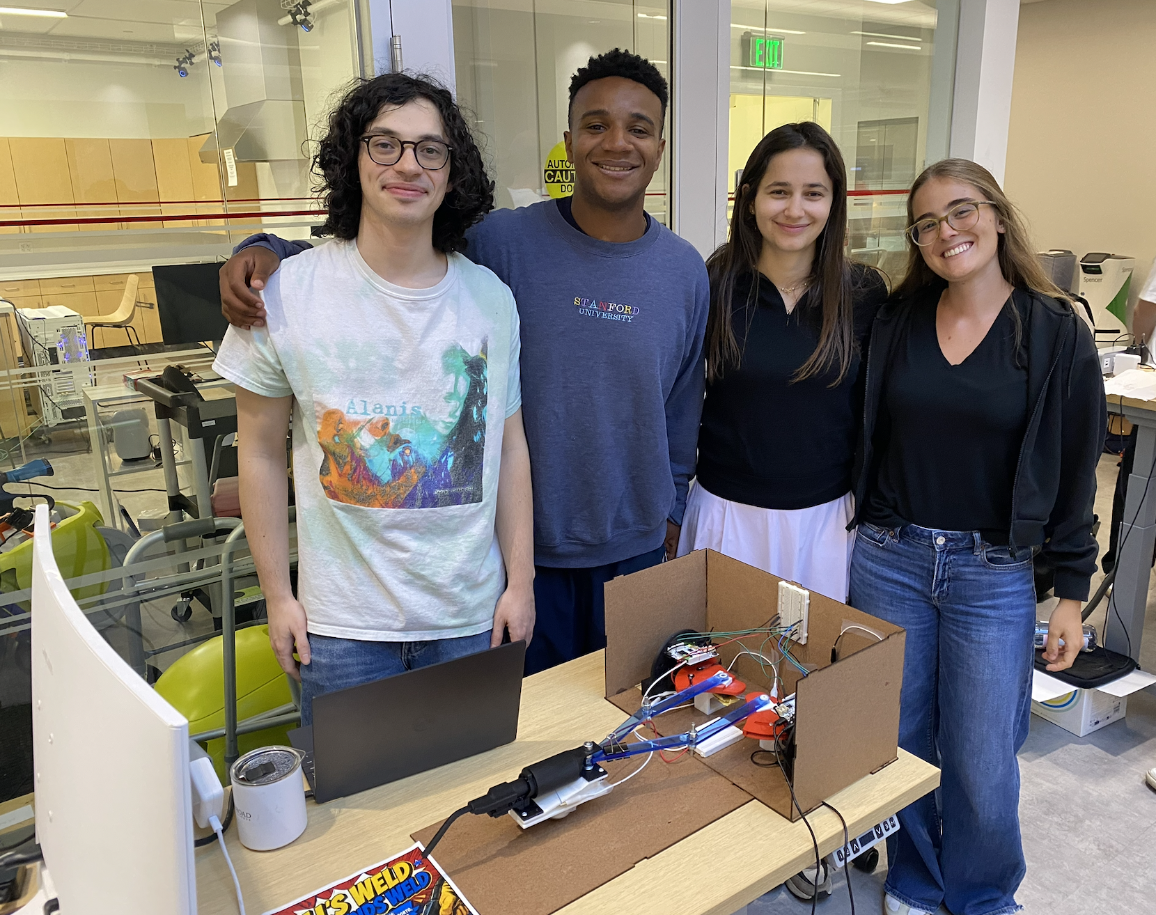
Team at the open house
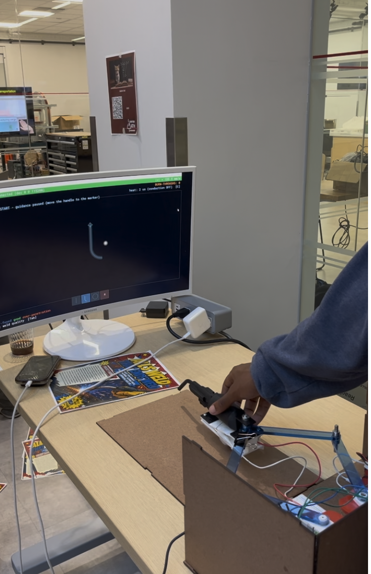
All's Weld that Ends Weld set-up
All's Weld that Ends Weld
Project team member(s): Kilas Gallimore, Victoria Porto, Carolina Carvalho, Alaz Cig
Our project is a haptic welding simulator designed to improve accessibility and effectiveness in welding training. Traditional welding instruction requires close supervision, extensive safety precautions, and significant material consumption, which can limit practice opportunities and increase training costs.
To address these challenges, we developed a haptic welding training system that simulates the resistance, torch dynamics, and material interaction forces experienced during real welding. The system provides force feedback for path correction, helping users maintain proper torch positioning and trajectory. Additionally, ERM motor vibration feedback alerts users to excessive welding speed and defects such as blowthrough. Visual feedback is also incorporated, allowing users to track their welding path in real time, while color-coded indicators communicate whether the welding speed is within the desired range.
By combining force, vibration, and visual feedback, the simulator enables users to develop proper motion control and welding techniques in a safe, repeatable and cost-effective training environment.
On this page... (hide)
Introduction
Traditional welding instruction requires close supervision, extensive safety precautions, and significant material consumption, which can limit practice opportunities and increase training costs. Different welding simulating devices have been designed to mitigate these challenges, usually focusing on maintaining a proper electrode angle, maintaining a good arc, and tracking or staying in the puddle. However, they provide mostly visual or audio feedback to trainees, and only provide performance feedback to the user after the simulated procedure. Few commercial systems incorporate haptic feedback, despite its importance for delivering real-time guidance and more closely replicating the tactile conditions of real-world welding.
To approximate real-world experience and provide meaningful feedback to trainees, our system uses two DC motors to deliver kinesthetic force feedback for path correction, along with one ERM motor that simulates welding sensations and provides feedback on both motion speed and blowthrough.
Background
Different welding simulating devices have been designed and exist since the 1970s (Wang et al., 2006). These usually focus on maintaining a proper electrode angle, maintaining a good arc, and tracking or staying in the puddle.
Although several technologies have been developed for this purpose, they provide mostly visual or audio feedback to trainees, and only provide performance feedback to the user after the simulated procedure. Most commercial welding training systems today incorporate comprehensive visual simulation features, including the ability to select appropriate electrodes, practice various welding methods, work in different welding positions, and adjust welding parameters such as current, voltage, and wire feed speed.
Some commercial systems have begun to incorporate limited haptic feedback. The Weles Welding Simulator, for example, features haptic gloves that provide thermal feedback. However, there still is no path correction or force feedback to guide proper welding technique during the training process.
Wang et al. investigated a haptic welding training tool built using a Phantom device with 6 DOF in a paper published in 2006. The haptic feedback incorporated in this device includes forces to simulate a realistic welding environment and forces to provide corrective feedback and guidance to users.
In the first category - to replicate a realistic environment - the device simulates the weight of the torch through a constant downwards force and a pull towards the metal base that varies with arc length using an exponential function and decays to zero when arc length is zero.
In the second category - training assistance - the device uses PD control to lightly guide the user. This includes directional / positioning through forces to guide the user to the correct arc length and path in addition to travel speed control, to ensure the user is moving at the ideal speed along the weld.
This device pre-defines the moving path, travel speed and arc length in order to correct the user accordingly and tracks the user�s location to find the user error. While Wang et al.'s system demonstrated the feasibility of haptic welding training, it had several limitations, one of the largest being its use of the Phantom system, which is very expensive and can be inaccessible.
Shankhwar et al. also investigated a visuo-haptic system for welding training, and claimed that studies have demonstrated the effectiveness of visuo-haptic in various manufacturing training processes (Shankhwar et al., 2022). Their training begins with a VR module, in which welding tools are simply demonstrated on a worktable along with safety instructions. After this, users can begin practicing, but the only form of haptic feedback they receive is kinesthetic force feedback.
Therefore, although there has been research published proving that haptic feedback can improve welding training, progress is limited, and there is the need for a more complete and realistic solution to guide welders through the process.
Methods
Hardware Design and Implementation
Mechanical Structure � Pantograph Linkage
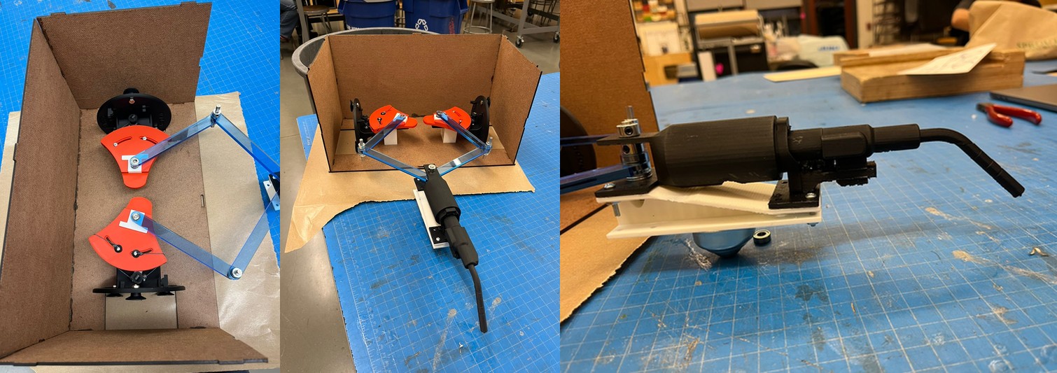
The core mechanical structure is a 2-degree-of-freedom pantograph consisting of four laser-cut acrylic links [4, 5, 6, 7]. The links are connected at their joints using embedded ball bearings, with D-shafts passing through two stacked links at each joint to couple them. C-clamps on the top and bottom of each joint secure the assembly and prevent axial separation.
Actuators � Cannibalized Hapkit Capstan Devices
Two Hapkit capstan devices [8, 9] serve as the actuators at the base of the pantograph. The Hapkit is a well-documented open-source device; only the modifications made to it are described here. The top portion of each capstan was removed and the red capstan component was reoriented to expose its T-shaped geometry, which was used to couple the capstan directly to its respective pantograph link [6, 7]. This coupling was secured using a bolt and super glue to enforce a rigid connection, ensuring that rotation of the capstan produces rotation of the attached link as a single rigid body. Each Hapkit's capstan is connected to a rotating magnet, and an onboard magnetic (magneto) sensor reads the magnet's angular position to determine how far the capstan has rotated. The two Hapkit assemblies are housed within a Duron (MDF) box structure that forms the base of the system.
End Effector � 3D Printed Welding Torch
The end effector is a 3D printed welding torch handle [1], based on an open-source STL geometry that was augmented for this project. A cavity was added to the underside of the handle to house an ERM (Eccentric Rotating Mass) vibration motor, which was glued in place to provide haptic feedback to the user during simulated welding. The two upper pantograph links [4, 5] connect to the base of the torch handle. To prevent the four-bar linkage from acting as a cantilever, a 3D printed coupler [2] was added to the torch assembly to mount a ball caster wheel [3] underneath, allowing the torch to translate freely across the 2D surface of the table while remaining supported.
Electronics and Sensing
Each Hapkit [8, 9] is driven by its own Arduino Uno microcontroller [10, 11], which interfaces directly with the Hapkit's motor driver and magnetic sensor. The two Arduino Unos [10, 11] communicate with each other via I2C, routed through a central breadboard [12]. The central breadboard [12] also serves as the junction point for wiring the ERM motor to the Hapkit boards. Both Arduinos are programmed via USB flash from a host computer.

System Analysis and Control
The software converts two joint angles, sampled continuously from the Hapkit sensors, into three outputs: corrective torques on the Hapkit motors, vibration cues on the ERM motor, and a rendered welding scene with sound.
Architecture
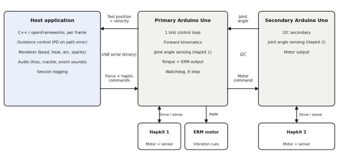
The software is split into two tiers. The primary Arduino runs a 1 kHz control loop: it reads its own magnetic angle sensor, polls the second joint angle from the secondary Arduino over I2C, computes the forward kinematics of the linkage to obtain tool position and velocity, and applies the commanded motor torques and ERM duty cycle. The same loop enforces safety - a safety check zeroes all forces if host commands stop arriving and an emergency stop latches until the user re-arms. The host application, written in C++ on the openFrameworks toolkit, exchanges state and commands with the primary Arduino over a binary serial link, and runs guidance control, graphics, and audio once per rendered frame. This split keeps the timing-critical force loop on dedicated hardware while the PC handles path logic and feedback rendering without real-time constraints.
Force Guidance
Reference paths (lines, arcs, and curves) are loaded from a path library and the user selects one to run. Each frame, the controller computes two errors: the perpendicular distance from the path, and the difference between the tool's travel speed and a target speed. A proportional-derivative law on the perpendicular error acts as a virtual spring-damper pulling the tool back toward the seam path, the proportional term corrects the speed along it, and the resulting force is mapped to joint torques through the Jacobian transpose of the linkage with safety limits at slippage force and singular positions. Forces ramp in and out gradually on arming and disarming rather than engaging at full strength which was essential for user experience.
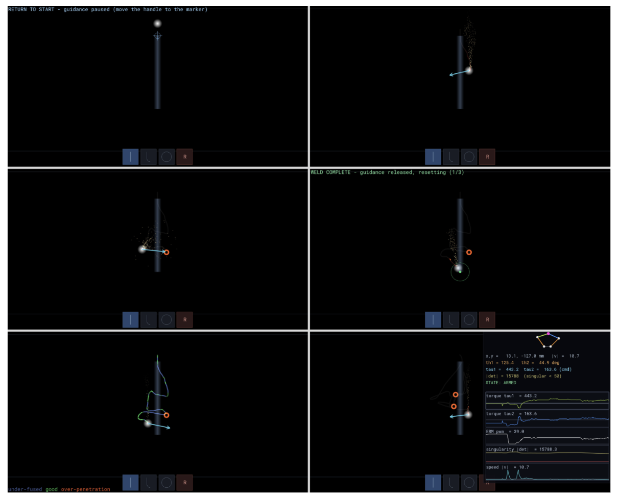
Feedback
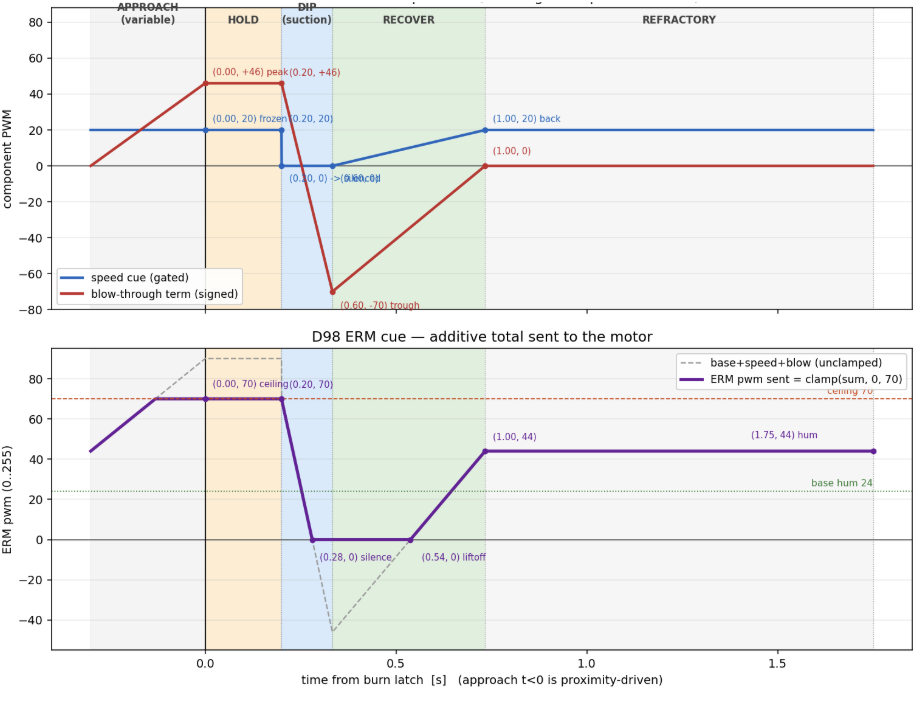
The trainer teaches two skills - staying on the seam and holding the correct travel speed. Each is communicated to the user through several channels at once. Path feedback is haptic and visual: the guidance force physically resists deviation, while the screen shows the reference path and an arrow indicating the direction and magnitude of the applied corrective force. Speed feedback spans all three channels: the ERM vibrates most strongly when the tool is stationary and falls quieter at the target speed; a one-time blow-through envelope (rising buzz, peak, dip, recovery) fires when the torch dwells too long in one spot; the crackle rate of the welding audio varies with travel speed; and the bead drawn behind the torch is colored by a simple heat model, so correct speed leaves a bright uniform bead while dwelling darkens and burns it, making the finished bead a persistent record of the run. Distinct sounds mark run completion and return-to-start, and the looped arc hiss plays only while the system is armed, so state changes register without looking at the screen.
Development Tools
The input layer is abstracted behind a common interface: the same program runs from the live serial setup, from the mouse, or from a recorded session log. The system can therefore be developed and tested without hardware. A debug mode displays critical information such as simulated kinematics, motor outputs, and sensor inputs.
Demonstration / Application
In our demo, open house attendees used the system to complete simulated welding tasks. Users followed predefined welding paths while receiving real-time force, vibration, visual, and audio feedback. The kinesthetic guidance helped users stay on the weld path, while visual indicators and vibration cues provided feedback on welding speed and errors such as blowthrough.
The demonstration showed the system's ability to teach path-following and speed control in a safe, repeatable environment. User feedback indicated that the force guidance felt intuitive and effective, highlighting the simulator's potential for use in vocational training programs, technical schools, and introductory welding education.
Results
Overall, the system was well-received at the open house demonstration. The kinesthetic feedback � where the system pushes the user back toward the correct welding path � was noted as feeling very natural and effective. The pantograph mechanism itself performed without any noticeable physical issues; motion across the 2D workspace felt smooth and free when no kinesthetic forces were being applied, and all programmed welding paths were designed to operate within the pantograph's reachable workspace.
The haptic simulation of torch-blowing and blow-through welding events via the ERM motor was less successful. User feedback indicated that the ERM was too weak to convincingly simulate either of these experiences, suggesting that a stronger vibration actuator would be needed in a future iteration. From a practical standpoint, users acknowledged that the system's 2-DOF constraint limits its applicability to real-world welding, which typically involves more degrees of freedom. However, there was general agreement that the system could serve as a useful training tool in 2D welding contexts, helping users develop an intuition for correct welding patterns and learn to maintain an appropriate pace during the welding process.
Future Work
The current system establishes a functional proof-of-concept for haptic welding training, and the next steps focus on validation, hardware refinement, and expanding simulation fidelity.
The most immediate next step is user validation. A structured study comparing training outcomes between novice welders using the simulator versus traditional instruction: measuring metrics such as bead consistency and travel speed control would quantify the system's training value and identify which feedback modalities contribute most.
On the hardware side, replacing the current ERM motor with a higher-amplitude vibration actuator, such as a linear resonant actuator (LRA) or voice coil, would enable greater contrast between feedback states. In particular, the blowthrough signal could be made significantly more intense and dramatic, making the consequence of the error more memorable which would reinforce correct behavior across sessions. The force feedback mechanism could also be extended to simulate torch weight and gravitational pull toward the workpiece, more closely replicating the Phantom-based system described by Wang et al. while remaining cost-accessible. Increasing the system from its current 2-DOF configuration to 3-DOF would also allow the simulator to also resist out-of-plane torch motion, more fully replicating the spatial constraints a welder navigates.
On the software side, expanding support to multiple weld joint types (butt, fillet, lap) and welding positions (vertical, overhead) would capture the meaningfully different torch dynamics each presents. Logging user trajectory, speed, and error data per session would enable progress tracking over time, which could be a key feature for structured training. Finally, the visual feedback display could be developed into a more complete simulation environment, integrating a weld pool visualization that responds dynamically to torch speed and position, giving users the same visual cues present in real welding. The visual feedback display could really show the heat transfer properties of the material.
Files
References
Wang, Yizhong, et al. "Study on Welder Training by Means of Haptic Guidance and Virtual Reality for Arc Welding." Proceedings of the 2006 IEEE International Conference on Robotics and Biomimetics, IEEE, 2006, pp. 954-958, doi:10.1109/ROBIO.2006.340145.
Shen, Kuan, et al. "Development of a Virtual-Haptic Integrated System for Improving Training Outcomes of Novice Welders." The International Journal of Advanced Manufacturing Technology, vol. 121, 2022, pp. 249-265, doi:10.1007/s00170-022-09328-4
"WELES Welding Simulator." Flint Systems, https://flint.systems/weles-welding-simulator/. Accessed [05/25/2026]
Appendix: Project Checkpoints
Checkpoint 1
For our first project check-off, we set off to have a good understanding / sketches of our design. This goal was met by us discussing design concepts and eventually choosing one that we all liked and thought would be feasible within the project scope. Our sketches are show below.
Attach:Sketches .pdf
Four our second goal, we wanted a robust list of components to procure. This goal was met by creating a BOM for our project.
Attach:ME 327 Component List.pdf
Lastly, we wanted to schedule out mini checkoff for ourselves to ensure we are staying on track. This goal was met , and we have outlined our project timeline below.
Attach:Project Timeline.pdf
Checkpoint 2
The goal for this checkpoint was to fabricate all mechanical components and to complete the hardware assembly.
The only remaining work from the timeline is to complete the link to Hapkit connection.