

2026-Group 8
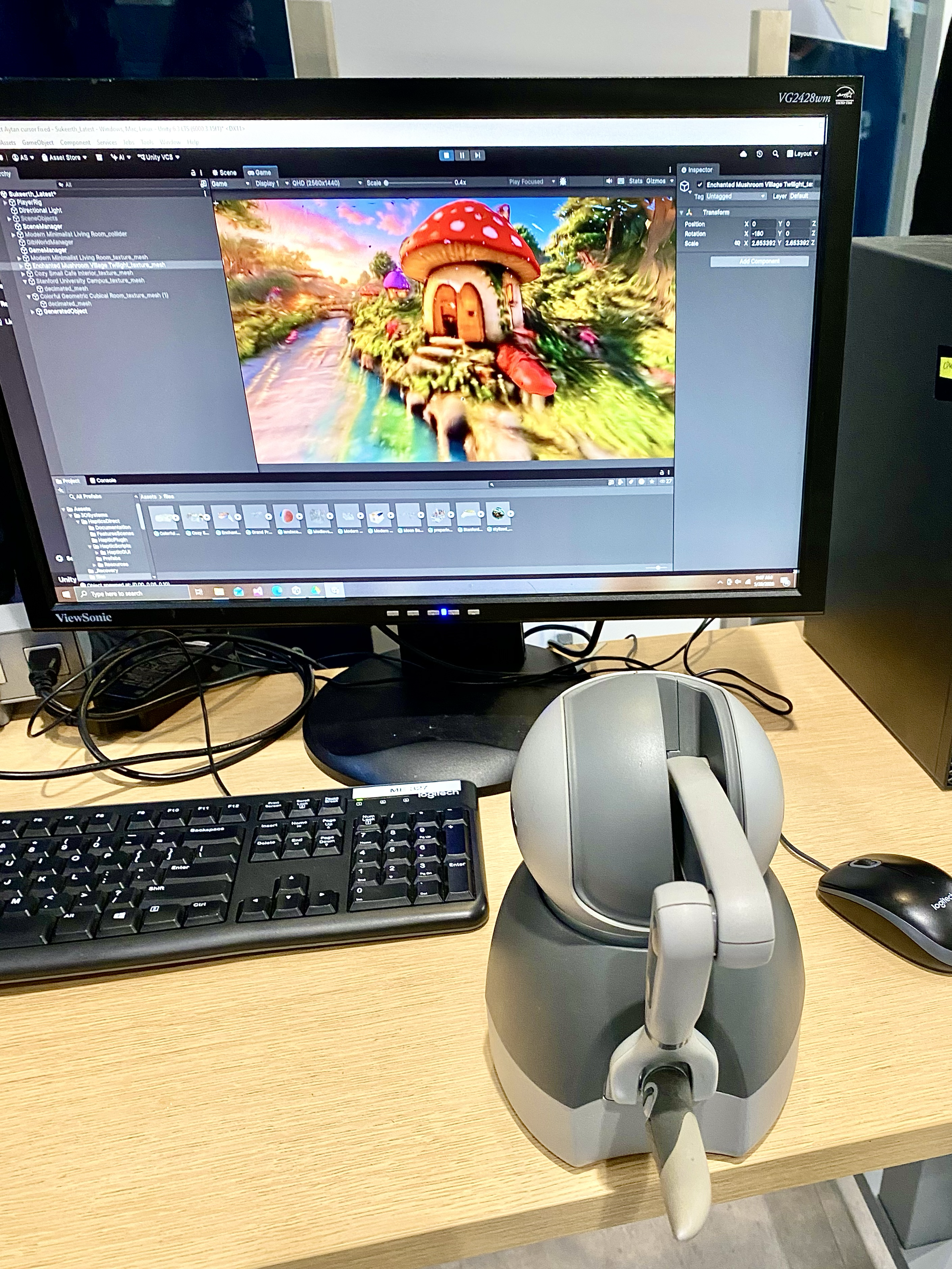
Touch World Setup on demo day.
TouchWorld: Haptic Exploration of AI-Generated 3D Environments
Team members: Aytan Sadirova, Herron Ha-Vi Nguyen, Marie Imad, Sukeerth Ramkumar
TouchWorld is a haptic exploration system that lets users physically feel AI-generated 3D environments through a robotic stylus, bridging the gap between the rapid advances in generative AI and the largely untapped potential of the sense of touch. Motivated by the belief that virtual worlds should be felt, not just seen, the project set out to make haptic technology genuinely accessible with no engineering background, 3D modeling software, and technical setup required. The system pairs a curated library of richly detailed AI-generated environments with two speech-driven generative pipelines: full-scene world generation through the World Labs Marble API (approximately 6 to 7 minutes end-to-end) and in-scene object insertion through Shap-E (approximately 90 seconds), all rendered through force feedback at 1 kHz using a 3D Systems Touch device. Built by a four-person team as part of ME327: Design and Control of Haptic Systems, TouchWorld was first demonstrated at the Haptics Open House in May 2026, where visitors experienced the level of geometric detail they could feel through the stylus.
On this page... (hide)
Introduction
The sense of touch is the most intimate channel through which humans interact with the physical world. Yet despite decades of progress in haptic display technology, feeling a virtual environment has remained the exclusive domain of specialists: it requires either expensive custom hardware, expert knowledge of CAD modeling, or both. For the vast majority of people, virtual worlds have always been something to look at, never something to touch.
TouchWorld challenges this assumption directly. The system enables any user, regardless of engineering background or technical familiarity, to navigate a richly detailed AI-generated 3D environment and feel its surfaces, edges, and geometry through a 3D Systems Touch haptic stylus. The experience requires no setup and no prior knowledge of haptics. Users can also describe a full environment or an individual object in natural language: a spoken world prompt can be turned into a haptic-ready scene through World Labs (on the order of 6 to 7 minutes), while a spoken object description can be generated with Shap-E and felt at the stylus within approximately 90 seconds, without CAD modeling or technical expertise.
This is made possible by two converging developments. First, generative 3D modeling platforms such as Marble AI can now produce high-resolution collision meshes from a single text prompt, at a level of geometric detail that would take a skilled modeler days to produce manually. Second, high-fidelity haptic devices such as the 3D Systems Touch provide sufficient force resolution at the fingertip to convey meaningful surface geometry in real time. TouchWorld connects these two capabilities end-to-end, with our team handling all geometry processing, coordinate alignment, mesh decimation, and force rendering configuration in Unity so that the user-facing experience is entirely seamless. 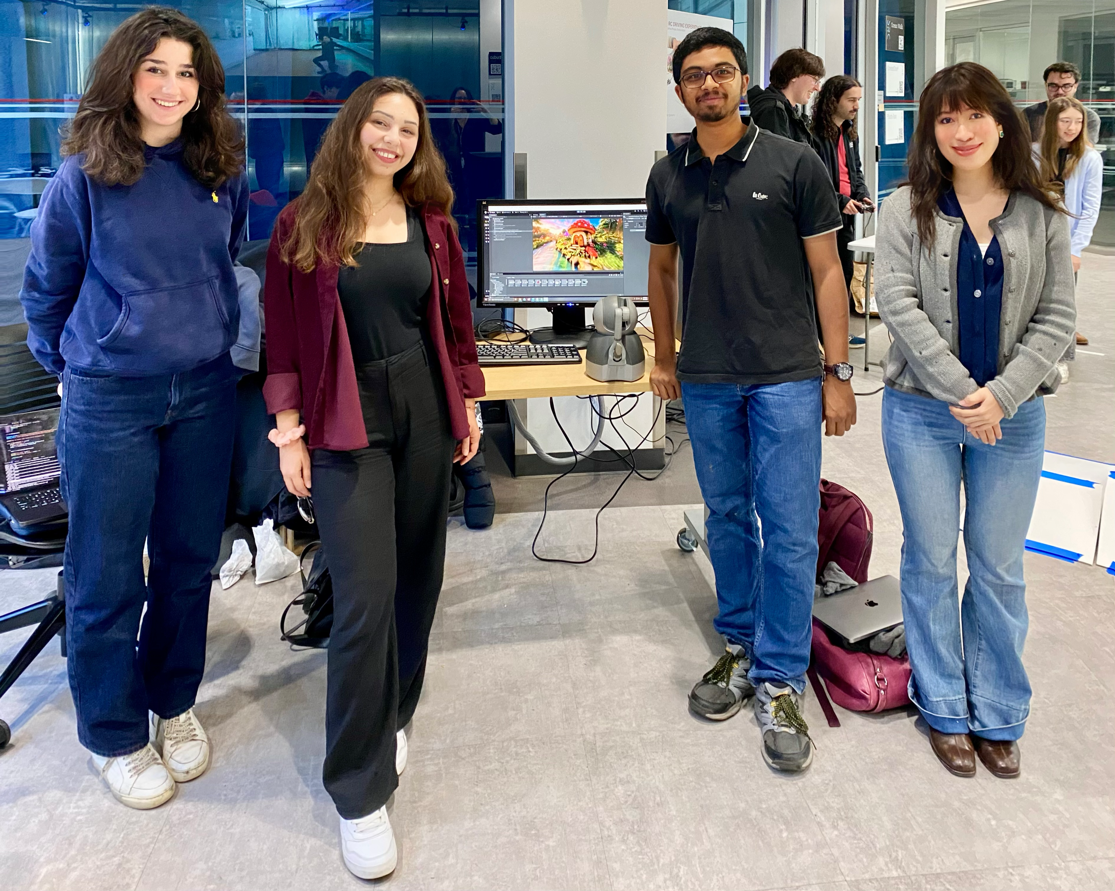
Team with Touch World Setup on Haptics Open House Demo day.
From an ME327 perspective, realizing this vision demands rigorous treatment of haptic rendering algorithms, discrete-time control stability, device dynamics, as well as real-time system integration. The 3D Systems Touch is well suited to this application: its three-degree-of-freedom force output, 1 kHz control loop, and OpenHaptics SDK expose precisely the low-level actuator access necessary for stable rendering of complex imported geometry. The result is a system that is simultaneously technically rigorous and genuinely accessible, demonstrating that haptic display need not be a specialist tool but can be as intuitive and expressive as the human voice.
Background
Haptic rendering of geometric environments has been studied since the seminal work of Zilles and Salisbury (1995), who introduced the god-object (proxy) method: a virtual point constrained to the surface applies a spring force proportional to its displacement from the device tip, providing a simple and robust contact model for polygonal meshes. The stability of this approach under digital control was formalized by Colgate and Brown (1994), who derived the Z-width metric and showed that the maximum renderable stiffness is bounded by the haptic loop rate and total system damping. This constraint is the central engineering challenge of TouchWorld.
For high-polygon-count geometry, brute-force triangle search is computationally intractable at 1 kHz. Two established solutions are relevant here. Adams and Hannaford (1999) demonstrated voxel-based signed distance field (SDF) representations that reduce contact queries to O(1) lookups regardless of mesh complexity. Alternatively, Ho et al. (1999) showed that perceptual sensitivity to haptic geometric error is limited, justifying the use of decimated proxy meshes for collision at reduced resolution while preserving visual fidelity in the render mesh. TouchWorld adopts this dual-mesh strategy.
The concept of walkable haptic environments has been explored in architectural contexts. Laycock and Day (2003) demonstrated interactive haptic walkthroughs of building models, establishing the feasibility of scene-scale force rendering. More recently, the emergence of Gaussian Splat representations (Kerbl et al., 2023) has enabled photorealistic real-time rendering of AI-generated scenes, though haptic integration of Gaussian Splat assets has not been previously demonstrated. TouchWorld bridges this gap by pairing Gaussian Splat visual rendering with triangle-mesh haptic collision derived from the same generative pipeline, delivering both photorealistic appearance and physically meaningful force feedback from a single generative source.
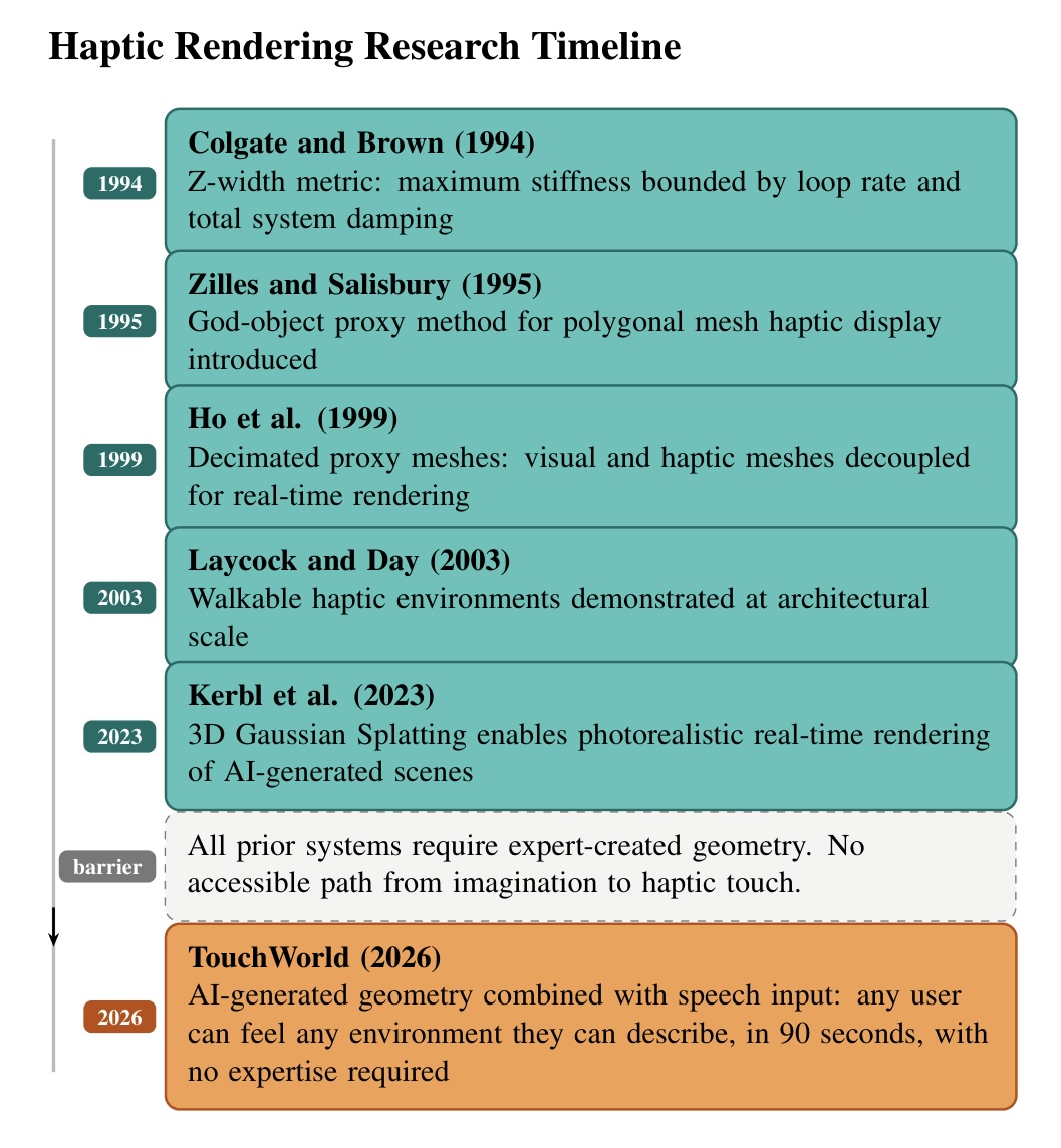
Figure 1: Haptic rendering research timeline from 1994 to 2026. Each milestone built toward richer force rendering, but every system required expert-created geometry. TouchWorld is the first to eliminate this barrier through generative AI and natural language input.
Despite these technical advances, a fundamental barrier has persisted across all prior haptic display systems: the assumption that haptic-ready geometry must be produced by experts. Every system described above requires a trained engineer or artist to first create a 3D model using CAD software or laser scanning, a process that can take hours to days per asset, demands significant technical skill, and places haptic content creation firmly out of reach for the general public. This bottleneck means that haptic technology, despite decades of research, has remained largely confined to specialist laboratories and has never fully delivered on its promise as a universal human-computer interface.
TouchWorld is motivated by the conviction that this barrier is not technical but paradigmatic. Humans are inherently creative and deeply motivated to shape their own experiences with technology. Research in human-computer interaction consistently shows that users engage more deeply, persist longer, and report greater satisfaction when they have authorship over their digital environments (Deterding et al., 2011; Malone, 1981). Yet haptics has never offered this. You could feel a virtual object, but only if someone else had already built it for you.
TouchWorld changes this on two fronts. Our system provides with a curated library of ten high-resolution 3D environments generated using Marble AI, including a magical mushroom village, an F1 race circuit on a clifftop, a reimagined Renaissance Stanford University campus, reimagined Starry Night painting by famous French painter Vincent Van Gogh, etc., each requiring approximately one hour of generation time and representing a level of geometric richness that would take days to produce manually. These environments have been pre-processed by our work as we imported them into Unity, aligned to the correct coordinate frame, decimated into haptic proxy meshes, and configured for real-time force rendering. Visitors at the open house can explore them immediately through touch, with no setup or technical knowledge required on their part.
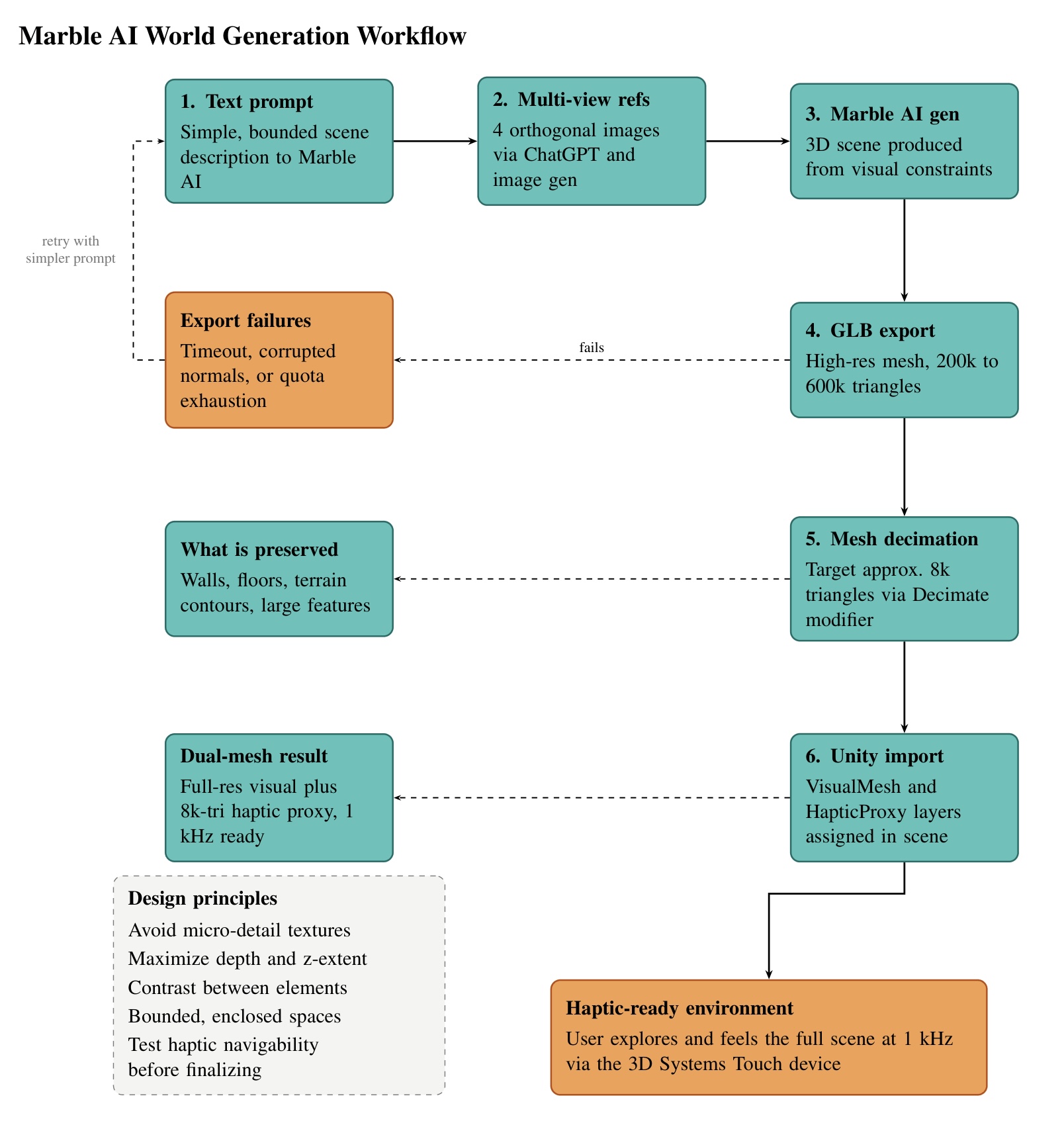
Figure 2: Marble AI world generation workflow. The pipeline moves from text prompt through multi-view reference image generation, 3D scene generation, GLB export, mesh decimation, and Unity import. Export failures trigger a retry loop with a simplified prompt.
TouchWorld also implements a speech-driven world-generation pipeline (Section III) that submits natural-language prompts to the World Labs Marble API and loads the resulting geometry into Unity automatically. More significantly for rapid in-scene authoring, TouchWorld introduces a 90-second object insertion pipeline that puts small-scale generative haptic content directly in the hands of any user. During exploration, a user simply speaks the name or description of any object they wish to feel. Within approximately 90 seconds, a fully haptic-ready GLB mesh is generated, inserted at the cursor tip, and immediately feelable. There is no CAD software to learn and no technical expertise required of any kind. A child can ask for a mushroom and feel its curved cap a few moments later. A designer can conjure a product concept and feel its form before a single prototype is built. The creative intent of the user, expressed as naturally as speech, becomes the sole authorship requirement for a complete haptic experience. This 90-second generation workflow represents a genuine discontinuity from all prior work in the field, where haptic content creation has always been a prerequisite skill rather than an effortless attempt.
The speech-driven object insertion component of TouchWorld further places it at the interconnection of haptics and embodied AI. Prior multimodal haptic systems have combined touch with audio (Gallace and Spence, 2014) and vision (Lederman and Klatzky, 2009). However, none have coupled natural language input with real-time generative geometry and force feedback in an accessible, user-facing system. TouchWorld articulates a new design principle for the field: haptic systems should be as expressive and accessible as the human imagination itself. The measure of success is not whether an engineer can feel a carefully modeled mesh, but whether anyone, anywhere, can feel whatever they can imagine.
Methods
I. Hardware Design and Implementation
1. Physical Setup
TouchWorld requires a single 3D Systems Touch haptic device (formerly Sensable PHANToM Omni), connected via USB to a Windows PC. The device provides three-degree-of-freedom force feedback with a maximum output force of 3.3 N. It is placed on a flat desktop surface at comfortable arm reach, with its base oriented so the device workspace aligns with the on-screen forward direction. No custom mechanical fabrication is required. A standard keyboard and mouse handle locomotion input; the Touch stylus controls only the haptic cursor.
The workstation must run Windows 10 or Windows 11. Linux and macOS are not supported because the 3DSystems HapticsDirect Unity plugin and Windows System.Speech library are Windows-only dependencies. Before launching Unity, plug in the Touch device and confirm it is recognized in the 3D Systems Control Panel; the plugin will fail silently if the driver is not active.
2. Software Stack
The following must be installed before opening the Unity project:
- Unity 6.3 LTS (Windows, 3D URP template)
- OpenHaptics Academic SDK 3.5.0 (installs the device driver and native C++ libraries)
- 3DSystems HapticsDirect Unity Plugin v1.0 (imported via local disk into the Unity project)
- glTFast (imported via Unity Package Manager; handles runtime GLB loading)
- Windows System.Speech (built into .NET on Windows; no separate install required)
- Python 3 with faster-whisper, sounddevice, and requests (World Labs world-generation pipeline; see Section III)
| Component | Version / Details |
| Haptic device | 3D Systems Touch (3-DOF, max 3.3 N) |
| Haptic SDK | OpenHaptics Academic 3.5.0 |
| Unity plugin | 3DSystems HapticsDirect v1.0 |
| Rendering engine | Unity 6.3 LTS |
| GLB importer | glTFast (Unity Package Manager) |
| World speech-to-text | faster-whisper (local transcription, 30 s capture) |
| World generation API | World Labs Marble API (marble-1.1) |
| Object speech-to-text | Google Speech Recognition API (Mac pipeline, Section VI) |
| Operating system | Windows 10 / 11 (Unity + haptics); Python host for world gen |
3. System Workflow
The end-to-end system workflow is shown in Figure 3, including six stages from user input through haptic feedback.
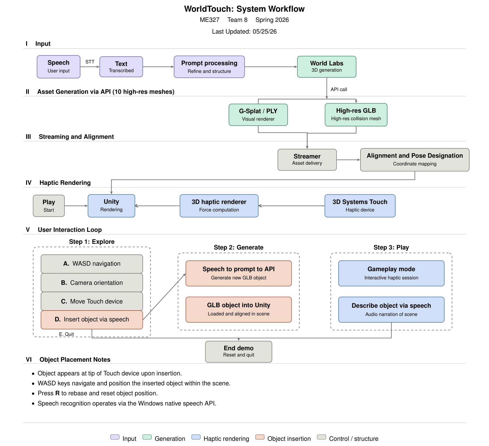
Figure 3: TouchWorld system workflow. Stage I captures speech and transcribes it to text (faster-whisper for worlds; separate stack for objects). Stage II calls the World Labs Marble API and downloads a collider mesh GLB, or generates a small object with Shap-E. Stage III places the finished GLB on disk for Unity to detect. Stage IV loads the mesh at runtime, applies haptic colliders, and drives the Touch device at 1 kHz. Stage V describes Explore, Generate, and Play interaction modes. Stage VI notes object placement at the stylus.
II. Environment Library and Dual-Mesh Architecture
1. Environment Library
For the Haptics Open House demonstration, TouchWorld relied on a pre-built library of ten 3D environments rather than waiting for live world generation per visitor. Each environment was produced using Marble AI (marble.ai), which exports photorealistic 3D scenes as GLB files. Assets were imported into Unity, aligned to the haptic coordinate frame, decimated into proxy meshes in Blender, and configured for stable force rendering (dual-mesh layout below). This library path provides immediate, repeatable exploration without the approximately 6 to 7 minute latency of the automated World Labs API pipeline described in Section III.
Separately, the project implements on-demand world loading: when a new collider mesh GLB is written to a shared watch folder on disk, Unity polls that folder at runtime, imports the file with glTFast, centers and scales the scene, and attaches haptic colliders automatically. The open-house experience used the curated library; the watch-folder path demonstrates that any user-described world can be generated and felt once generation completes.
One important practical limitation of Marble AI is that scene complexity directly affects export reliability. Scenes with dense geometry, many distinct objects, or large outdoor areas frequently fail during the high-resolution GLB export step, either timing out or returning a corrupted file. In practice, simpler scenes with fewer distinct objects and cleaner geometry exported reliably, while highly detailed or large-scale scenes required multiple generation attempts or prompt simplification before a usable GLB was obtained.
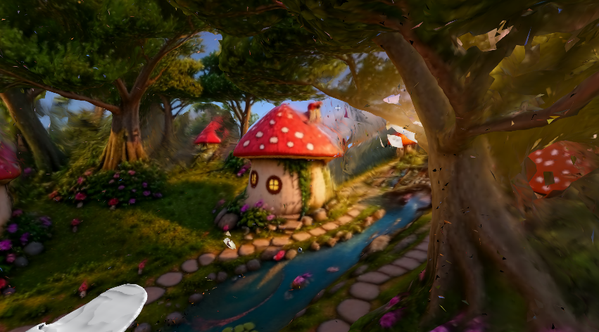
Figure 4: Enchanted mushroom village. Winding stone paths, a babbling brook, and dense forest canopy create a rich variety of surface types for haptic exploration.

Figure 5: Stanford campus reimagined in Renaissance style, featuring Hoover Tower, terracotta rooftops, wisteria-draped colonnades, and ornamental gardens at sunset.

Figure 6: Cliffside F1 racing circuit overlooking the Mediterranean. Tarmac straights, stone barriers, pit lane structures, and curb geometry offer a range of hard, flat, and curved haptic surfaces.

Figure 7: Grand Renaissance palace courtyard with an ornate inlaid marble floor, arched colonnades, and a central fountain. The patterned tile floor provides a large continuous surface ideal for demonstrating subtle surface texture variation through haptics.
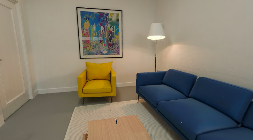
Figure 8: Modern living room interior. Flat walls, upholstered furniture, and a low coffee table offer contrast between hard and soft surface haptics.

Figure 9: Corner cafe and bakery. Counter edges, display cases, and cabinetry demonstrate haptic feedback on sharp-edged architectural geometry.

Figure 10: Spanish colonial courtyard modeled after Stanford's sandstone arcade. Arched colonnades and a central lawn provide large flat surfaces and curved architectural details.
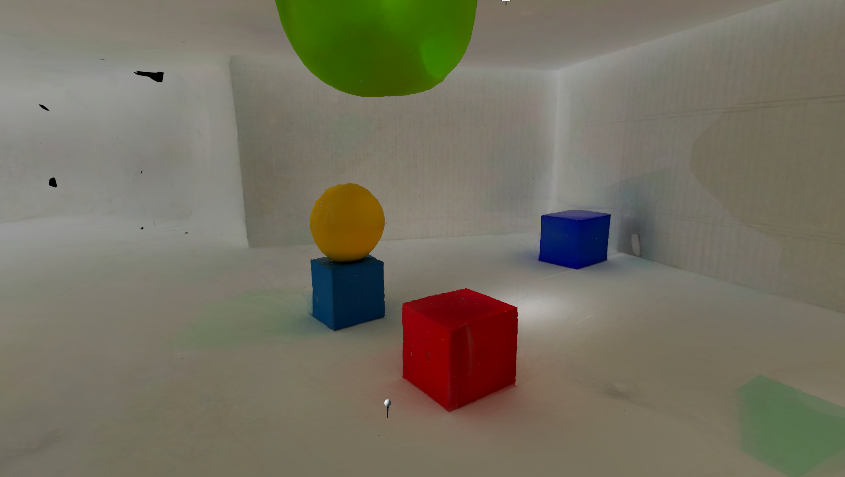
Figure 11: Geometric primitives scene used for haptic calibration and stiffness testing. Simple convex shapes isolate individual surface normals, making it straightforward to verify force direction and magnitude without geometric ambiguity.
2. Dual-Mesh Architecture
The central design challenge of TouchWorld is that AI-generated GLB meshes are far too dense for real-time haptic collision. A typical Marble AI environment contains between 200,000 and 597,000 triangles. Haptic collision detection must run at 1 kHz; running the scheduler against a 500k-triangle mesh causes it to miss deadlines and produces unstable, buzzing force output.
TouchWorld resolves this with a dual-mesh architecture: every environment is represented simultaneously by two separate mesh objects in the Unity scene hierarchy.
- VisualMesh: the full-resolution GLB mesh, rendered normally by the URP pipeline at 60+ Hz. MeshCollider is disabled. This mesh is never queried by the haptic scheduler.
- HapticProxy: a decimated version of the same geometry containing approximately 5,000 to 10,000 triangles. MeshRenderer is disabled (invisible to the camera). MeshCollider is enabled and assigned to the
HapticLayerphysics layer, which the HapticsDirect plugin is configured to query exclusively.
Decimation is performed in Blender using the Decimate modifier (Collapse mode) before importing library assets into Unity. The target is approximately 8,000 triangles, tuned to preserve walls, floors, and large terrain contours that the user would physically feel, while discarding fine surface detail that the Touch device cannot spatially resolve. In the library, each environment prefab contains two child objects: a full-resolution visual mesh (rendered, no physics collider) and a decimated haptic proxy (invisible, mesh collider on the haptic physics layer). Runtime worlds loaded from the watch folder use the API collider mesh directly; offline decimation remains recommended when triangle counts exceed stable haptic scheduling limits.
III. World Generation
1. Overview
Generating high-quality haptic-ready environments required significant experimentation with the Marble AI generative platform. Initial attempts used direct text-to-3D prompting, but results were inconsistent: some environments produced adequate geometry while others lacked the spatial coherence and surface detail necessary for meaningful haptic exploration. Flat or under-extruded geometry was the most common failure mode, producing scenes that were visually plausible from a fixed viewpoint but haptically sparse when navigated with the stylus.
2. Multi-View Reference Image Approach
A more robust multi-view reference image approach was developed to address the limitations of direct text prompting. Rather than relying on text alone, four orthogonal reference images of the target environment (front, back, left, and right views) were first generated using an image generation model and then provided to Marble AI as visual constraints for the 3D generation process. This technique substantially improved geometric consistency across the scene and produced environments with richer, more spatially coherent three-dimensional structure. A comparison of direct text-to-3D outputs versus multi-view reference image outputs is shown below.

Figure 12: Direct text-to-3D output (left) versus multi-view reference image output (right) for the same scene prompt. The multi-view approach produces substantially richer depth structure and more consistent surface normals, both critical for haptic exploration.
3. Design Principles for Haptic World Generation
Through iterative experimentation, a set of design principles emerged for generating environments that are both visually compelling and haptically rich:
- Avoid excessive surface micro-detail. Overly intricate textures such as fine leaf veining or fabric weave exceed the generative model's geometric capacity and produce noisy, inconsistent meshes. Simpler, bolder features generate more reliable geometry.
- Prioritize depth and z-extent. Each scene element must have sufficient three-dimensional volume, particularly in the depth direction, to produce meaningful force variation as the user moves through the space. Flat scenes are visually adequate but haptically uninteresting.
- Maximize geometric contrast between elements. Floors, walls, objects, and architectural features must differ sufficiently in height, curvature, and surface angle to produce perceptible force differences at the fingertip.
- Prefer contained, bounded spaces. Scenes with clearly defined walls and floors provide a richer haptic boundary structure than open landscapes. Indoor and semi-enclosed environments consistently produced more engaging haptic experiences than open-air terrain.
4. Export Reliability and Failure Modes
One critical practical constraint is that scene complexity directly affects export reliability on Marble AI. Scenes with very dense geometry, many distinct objects, or large outdoor areas frequently timed out or returned corrupted GLB files during the high-resolution export step, requiring multiple generation attempts or prompt simplification before a usable asset was obtained. In practice, the following failure modes were encountered:
- Timeout failures: large outdoor scenes with complex terrain exceeded Marble AI's export time limit and returned no file.
- Corrupted geometry: some exports contained inverted normals, non-manifold edges, or disconnected mesh islands that caused visual artifacts and erratic haptic force directions in Unity.
- Quota exhaustion: repeated generation attempts against the same scene type depleted the Marble AI generation quota, requiring fallback to Sketchfab (sketchfab.com) as an alternative GLB source.
Each candidate environment was therefore evaluated not only for visual quality but for haptic richness and export integrity before inclusion in the final library. Scenes that passed visual inspection but produced corrupted proxy meshes after decimation were discarded or regenerated with simplified prompts.
5. Runtime Speech-to-World Pipeline
Beyond the offline library workflow, TouchWorld connects spoken language to scene-scale haptics through an external Python pipeline and a runtime Unity loader. The two stages are deliberately decoupled: generation and file transfer happen outside the game engine; Unity only watches for a finished GLB and imports it when stable.
Speech capture and transcription. The user speaks a world description for approximately 30 seconds. Audio is recorded from the default microphone and transcribed locally with faster-whisper (OpenAI Whisper implemented via the faster-whisper library), running on CPU or GPU without a cloud speech API for this path. If no microphone is available, the same pipeline accepts a typed prompt so development and testing can continue.
World Labs Marble API. The transcript is sent to the World Labs Marble API (model marble-1.1). The client submits a text world prompt, polls the asynchronous generation operation (typically on the order of ten-second intervals), and retrieves world metadata when complete. The collider mesh GLB is downloaded from the API response URL. The file is written atomically (temporary file first, then rename) to a fixed watch directory so Unity never reads a partially written mesh.
Timing. End-to-end world generation, including API processing and download, requires approximately 6 to 7 minutes in practice. This dominates the user wait time. Unity import and haptic setup add only seconds once the file is stable.
Asset import packages. Unity requires additional packages to load generated asset formats used in TouchWorld. Runtime GLB loading is handled through glTFast, which imports the generated collider mesh into the Unity scene. PLY / Gaussian Splat visualization uses a separate Gaussian Splat package, which adds import and asset-creation tools to the Unity editor. These packages were installed through Unity's package workflow using Window -> Package Manager, either from a local package file or a GitHub URL. In the runtime path, Unity primarily imports the generated GLB mesh for haptic interaction; PLY and Gaussian Splat files remain part of the complementary editor/manual workflow for high-quality visualization.
Unity handoff. A runtime manager on the Windows Unity host polls the watch folder (default C:/HapticWorlds/) approximately once per second. When a new or updated GLB is detected and file size has stabilized, glTFast loads the scene, the mesh is centered and scaled into the haptic workspace, and colliders plus surface material descriptors are added on every mesh so the Touch device can render force feedback (contact geometry in Section IV). The previous generated world can be replaced automatically when a new file arrives.
Relation to the environment library. The library path (Section II) supplies curated, Blender-decimated proxies optimized for stable 1 kHz haptics at demo time. The runtime API path trades preparation time for authorship: any natural-language scene description can be felt after generation completes, often at higher triangle counts until optionally decimated offline. Gaussian Splat visual exports and full-resolution visual meshes from manual Marble workflows remain complementary assets; the automated API path used here delivers the collider mesh sufficient for haptic exploration.
IV. Haptic Rendering Pipeline and Contact Geometry
1. Architectural Overview
TouchWorld separates geometric contact detection from force synthesis across two independent real-time loops. The game engine's physics module resolves whether the virtual stylus intersects the haptic proxy mesh at the simulation rate (approximately 50 Hz). The OpenHaptics device scheduler, accessed through the commercial Unity haptics plugin, computes and applies actuator forces at 1 kHz on a dedicated servo thread. The engine answers where contact occurs and which surface properties apply; the native layer answers what force the user should feel. This division allows arbitrary AI-generated geometry to be imported without implementing a full haptic renderer in the application.
The signal path each cycle is: read device pose from the Touch encoders; map it into the virtual scene through the haptic workspace frame; drive a spherical collision proxy toward that pose; query the physics engine for contact points and normals on decimated proxy meshes (Section II); attach per-surface material and kinematic data to each contact; commit the list to the native renderer; output a three-degree-of-freedom force at the stylus tip on every servo tick. Section V analyzes force magnitude and discrete-time stability; this section documents the geometric pipeline that supplies those inputs.
2. Coordinate Frames and the Virtual Proxy
During exploration, the user's viewpoint and haptic workspace translate together under keyboard locomotion; the camera may rotate independently under mouse input. The device reports its end-effector transform in device coordinates. Each simulation step this is composed with the workspace frame:
T_world = T_actor * T_device
Contact locations sent to the native renderer are expressed in the inverse workspace frame and scaled to consistent physical units, so force directions remain coherent as the user moves through large scenes whose meshes may sit at arbitrary positions.
The physical stylus is not a simulated rigid body. TouchWorld uses a virtual proxy (a small sphere with an attached rigid body) as the collision probe. In free motion the proxy is repositioned to the target pose each step with zero residual velocity. On contact with a haptically tagged surface, the proxy pursues the device pose with a controlled force rather than snapping to it. That lag produces sustained overlap between sphere and triangle mesh, which the physics engine needs to report a stable contact manifold. Without overlap, no contacts are registered and the user feels nothing despite visual intersection. Proxy radius sets the effective cursor size; a maximum stiffness enforced at the proxy prevents any single surface from driving the device into instability.
3. Contact Detection in the Physics Engine
All haptic-interactive geometry carries a triangle mesh collider, a kinematic rigid body, and a surface material descriptor. Colliders exist only on decimated proxy meshes (Section II); full-resolution visual meshes are never queried.
When the proxy intersects a surface, NVIDIA PhysX runs a two-phase query each simulation step. Broad-phase bounding-volume hierarchies discard triangle pairs that cannot interact. Narrow-phase GJK, optionally followed by EPA, computes the minimum separation between the sphere and the nearest mesh triangles. The result is a contact manifold: one or more points mathbf{p}_i, each with an outward unit normal hat{mathbf{n}}_i perpendicular to the hit triangle. For vertices mathbf{v}_0, mathbf{v}_1, mathbf{v}_2:
n_face = normalize((v_1 - v_0) x (v_2 - v_0))
These face normals (not vertex normals used for shading) define the constraint direction. Sliding across triangle edges on a coarse proxy can change hat{mathbf{n}}_{mathrm{face}} abruptly; implications for perceived surface quality are discussed in Future Work. Contact lifecycle events (entry, sustained contact, exit) control when data are forwarded and when direct proxy tracking resumes.
4. Contact Records and Native Force Transmission
For each active collision, the integration layer walks all points in the manifold (typically one to four per pair). Each becomes a contact record with the following content.
Location and normal are transformed into workspace-local coordinates:
p_local = T_actor^-1 * p_i / s
n_local = normalize(T_actor^-1 * n_i)
Material parameters (stiffness, damping, static and dynamic friction, viscosity, optional spring anchor and constant bias) are read from the colliding object's descriptor. Stiffness is capped at the lesser of the object setting and the proxy maximum. Damping may be reduced briefly after initial impact to limit high-frequency buzzing. If the object moves, linear and angular velocity, mass, collision impulse, and timestep are included so the renderer can account for motion at contact.
Degenerate normals are discarded. When several points arise from one mesh object, a single representative contact per object is committed per step to avoid sending redundant constraints.
At the end of each physics update the previous contact list is cleared, the new records are registered with the native plugin together with a workspace-local stylus anchor (the reference for penetration depth), and the list is committed for the 1 kHz scheduler. Between physics steps the scheduler continues rendering from the last committed list. The closed-source plugin implements a god-object contact model (Salisbury et al., 2004): restoring force along hat{mathbf{n}}_{mathrm{local}} from stiffness and penetration depth, augmented by damping, friction, and viscosity; the same structure is analyzed in Section V. The application does not evaluate force magnitudes; it supplies geometry and material boundary conditions.
5. Surface Material Parameters
Every library environment, proxy submesh, and runtime-inserted object carries a material descriptor assigned at load or insertion time. Table 1 summarizes the parameters forwarded to the native layer at contact.
| Parameter | Physical interpretation |
| Stiffness | Surface hardness on [0, 1]; capped by proxy maximum |
| Damping | Energy dissipation; reduces contact oscillation |
| Static / dynamic friction | Resistance to starting and sustaining slide |
| Viscosity | Velocity-dependent drag through the surface |
| Spring magnitude and anchor | Pull toward a spatial reference point |
| Constant force magnitude and direction | Bias independent of penetration |
| Pop-through threshold | Force level above which stiffness is disabled |
Table 1: Surface material parameters and their roles at contact.
The normalized stiffness and damping configured here are the same quantities whose stability limits are derived in Section V. Section IV describes how contact geometry reaches the renderer; Section V describes when the resulting forces remain stable and perceptually convincing.
6. Unity Component Pipeline and Plugin Binding
The Unity side of TouchWorld acts as the authoring and synchronization layer for haptic interaction. It does not directly compute actuator forces. Instead, Unity organizes the imported scene into objects that the haptic plugin can interpret. Each touchable object is represented by a Unity GameObject containing a mesh, transform, collider, rigid body state, and haptic metadata.
At load time, imported GLB assets are inserted into the Unity hierarchy as ordinary mesh objects. If the GLB is used only as a physical proxy, its visual renderer can be disabled while its collider and haptic components remain active. This allows the visible scene and the haptic scene to be separated: the user may see a high-resolution visual model, while the haptic device interacts with a simplified collision mesh.
The haptic plugin reads the Unity object hierarchy through attached components. The Mesh Filter stores the imported mesh geometry, and the Mesh Renderer controls whether the GLB is visible in the scene. However, the Mesh Renderer does not make the object touchable. Touch interaction comes from the Mesh Collider and the haptic plugin components. The Mesh Collider defines the triangle surface used by Unity physics for contact detection, while the Haptic Material defines the surface-response parameters that are forwarded to the native haptic renderer.
The Unity-side binding can be summarized as:
Imported GLB mesh -> Unity GameObject -> Mesh Collider -> Haptic Collider -> Haptic Material -> Native plugin registration

Figure 13: Unity Inspector view of the selected decimated GLB proxy mesh. The object contains standard Unity mesh components, including Mesh Filter, Mesh Renderer, and Mesh Collider, together with the Haptic Material script used by the haptic plugin. The Mesh Collider defines the touchable triangle geometry, while the Haptic Material stores surface-response parameters such as stiffness and damping for the native haptic renderer.
If one part of this chain is missing, the object may fail to produce force feedback. For example, a collider without the required haptic plugin component may participate in Unity physics but may not be registered as a haptic surface.
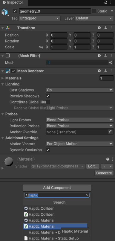
Figure 14: Adding the Haptic Material component from Unity's Add Component menu. This step attaches the haptic plugin's material interface to the imported mesh object, allowing surface parameters to be assigned and forwarded to the native backend during contact.

Figure 15: Unity hierarchy showing the haptic workspace and imported GLB proxy meshes. The PlayerRig contains the haptic workspace anchor, HapticActor, SimpleStylus, and HapticCollider objects that represent the device cursor in the scene. Each imported environment contains a decimated_mesh child, which acts as the simplified haptic proxy surface used for collision and force feedback.
The cursor-side hierarchy is separated from the scene-object hierarchy. The PlayerRig contains the virtual representation of the haptic device, including the workspace anchor, haptic actor, stylus model, and haptic collider. The SimpleStylus provides the visible cursor/stylus representation, while the HapticCollider acts as the physical probe used by Unity physics to test contact against touchable meshes. In contrast, the imported scene objects contain decimated_mesh children that represent the surfaces the cursor can touch. During runtime, the cursor-side collider moves with the physical 3D Systems Touch stylus, while the decimated mesh colliders remain fixed as environmental surfaces.
This hierarchy separates the moving haptic probe from the static haptic environment: PlayerRig defines the user/device side, while the decimated_mesh objects define the touchable world side.
7. Haptic Material as a Parameter Interface
The haptic material is different from a visual material. A visual material controls appearance, such as color, texture, transparency, and lighting. A haptic material controls physical response, such as stiffness, damping, friction, viscosity, pop-through behavior, and optional force effects.
The haptic material does not calculate force by itself. It stores parameters that are read by the plugin and passed to the native renderer. When the proxy contacts a tagged surface, the integration layer reads the material values from the Unity component and attaches them to the contact record.
In this sense, the mesh collider answers:
Where is the surface?
while the haptic material answers:
What should the surface feel like?
The native force renderer then uses these values during the servo-loop calculation. A larger stiffness value produces a stronger restoring response for the same penetration depth. A larger damping value dissipates more energy and reduces oscillation. Friction parameters affect sliding along the surface, while viscosity introduces velocity-dependent resistance.
This design keeps the scene editable from the Unity Inspector. Surface feeling can be tuned by changing object-level material settings without modifying the native force-rendering code.
8. Native Plugin and DLL Boundary
The haptic plugin contains both Unity-facing components and native compiled libraries. The Unity-facing layer exposes scripts, components, and Inspector fields inside the editor. The native DLL layer performs lower-level haptic operations that are not suitable for Unity's ordinary graphics or physics loop.
This boundary is necessary because haptic rendering requires a much higher update rate than Unity rendering. Unity visual frames and physics steps run at tens of hertz, while stable haptic force feedback requires approximately 1000 updates per second. The native DLL allows the haptic servo loop to run independently from Unity's frame rate.
This separation allows Unity to display and update the virtual cursor, while the native backend maintains the high-frequency force loop. Unity supplies scene geometry, transforms, contact records, workspace scaling, and material parameters. The native haptic backend uses these inputs to compute and transmit force feedback through the haptic device driver.
Because the commercial plugin and DLL are closed source, TouchWorld treats them as a native haptic backend rather than relying on their exact internal implementation details.
9. Location of Force Calculation
The final force calculation occurs inside the native haptic backend, not inside ordinary Unity scene scripts. Unity supplies the required geometric and material inputs, but the native plugin computes the actual force magnitude and direction sent to the device.
At each Unity physics update, the application provides the most recent contact state. This includes contact position, contact normal, material parameters, object motion data, and the workspace-local stylus anchor. Once this contact list is committed, the native scheduler reuses it during its faster servo loop.
Between Unity physics frames, the contact geometry may remain unchanged, but the physical stylus position continues to update at the haptic rate. Therefore, the DLL can continue calculating force using the latest device pose and the most recently committed contact information.
Conceptually, the native renderer evaluates a contact law of the form:
F = F_stiffness + F_damping + F_friction + F_optional
The stiffness term depends on penetration depth along the contact normal. The damping term depends on relative velocity. The friction term acts tangentially along the contact surface. Optional terms may include viscosity, spring attraction, constant bias force, or pop-through behavior.
The Unity application does not directly evaluate this equation every frame. It only supplies the boundary conditions needed by the equation. The native haptic renderer owns the real-time force synthesis step because it must satisfy the timing and stability requirements of the physical device.
10. File-Level Responsibility in the Haptic Stack
The files in the Unity haptic system can be grouped by their responsibility.
Unity scene files and prefabs store the object hierarchy, transforms, imported meshes, camera setup, collider assignments, and component settings. These files define what exists in the virtual world.
Imported GLB files provide the triangle geometry used for collision and haptic proxy interaction. If a separate PLY or Gaussian-splat representation is used, it provides visual appearance only, while the GLB remains the physical touch surface.
Unity C# scripts handle scene setup and synchronization. They may instantiate imported assets, align visual and haptic objects, assign colliders, update the proxy position, collect collision data, read haptic material settings, and call plugin functions to register contact records.
Haptic plugin components expose the haptic system inside Unity. These include device-management objects, workspace mapping components, cursor or proxy objects, haptic colliders, and haptic materials. They mark which Unity objects are touchable and define how they should behave during contact.
Native DLL files implement or wrap the low-level haptic backend. They communicate with OpenHaptics and the device driver, maintain the high-frequency scheduler, process committed contact records, calculate output forces, and send force commands to the physical haptic device.
The driver provides the final hardware interface. It reads encoder values from the 3D Systems Touch device and applies motor commands computed by the haptic renderer.
This layered file architecture can be summarized as:
Scene / prefab files -> Imported mesh files -> Unity C# scripts -> Haptic plugin components -> Native DLL files -> Device driver -> Physical haptic device
11. Runtime Execution Order
At runtime, Unity first loads the environment and constructs the scene hierarchy. Imported GLB meshes are placed in the scene, assigned transforms, and given collider components. Touchable objects are tagged with haptic plugin components and material descriptors. If a separate high-resolution visual representation is present, the visual object and haptic proxy mesh are aligned so that the visible object and touchable object occupy the same space.
When the user moves the physical stylus, the device driver reports the stylus pose to the native backend. The plugin maps this pose into the Unity workspace and updates the virtual cursor or proxy. Unity's physics step checks whether the proxy intersects any haptic collider. If contact exists, Unity extracts the relevant contact information and forwards it, together with the haptic material properties, to the native plugin.
The native scheduler then computes force at the servo rate. The computed force is sent through the driver to the 3D Systems Touch motors, producing the physical sensation of contact. Unity may update the visual cursor at the graphics frame rate, but the force loop continues independently at the haptic rate.
Thus, the system has two synchronized but unequal update loops: Unity updates the visible and geometric state, while the DLL-backed haptic scheduler updates the force output. The user experiences them as one continuous interaction because the plugin continuously maps device motion, contact geometry, and material response between the two layers.
12. Summary of Unity-to-Hardware Communication
The complete communication chain is a division of responsibility. Unity defines the virtual scene, imported meshes, object transforms, colliders, and material settings. The haptic plugin reads these Unity components and converts them into data structures that can be used by the native backend. The DLL maintains the high-frequency haptic scheduler and calculates the actual force response. The OpenHaptics driver sends the resulting force commands to the 3D Systems Touch device.
This architecture allows TouchWorld to use AI-generated 3D assets without writing a full haptic renderer inside the Unity application. Unity remains responsible for scene construction and contact geometry, while the native haptic plugin remains responsible for stable real-time force synthesis.
V. System Analysis and Control
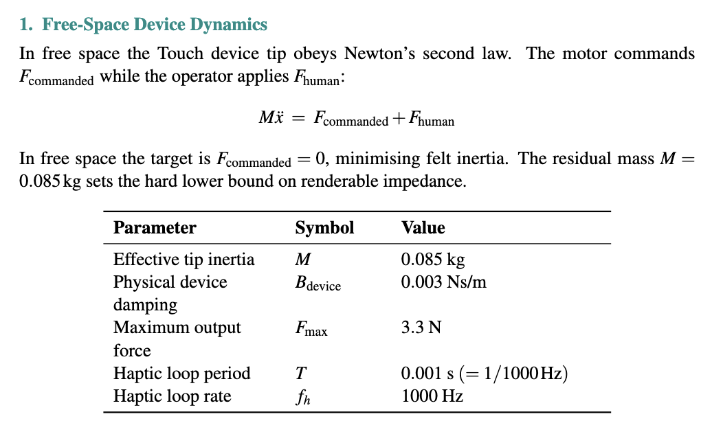
This free-space model is the foundation for understanding why virtual damping is necessary: the physical damping alone is so small (0.003 Ns/m) that it provides almost no stability margin for the discrete-time control loop, as the stability analysis below demonstrates.
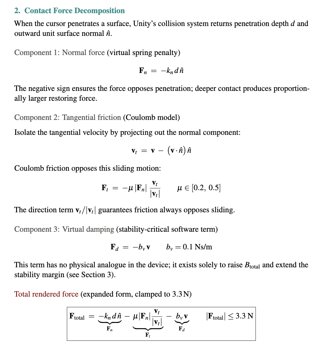
The expanded total force equation makes explicit why each term is important for our dynamics. The normal force term alone would produce a frictionless, slippery surface that feels unconvincing. The friction term adds resistance to sliding that makes surfaces feel materially distinct. For example, a stone floor feels different from a fabric sofa because mu differs. The virtual damping term is invisible to the user perceptually but is load-bearing for stability: without it the system would oscillate violently at any useful stiffness, as the 6 N/m physical-only limit shows. Together the three terms produce a force that is physically grounded, perceptually rich, and numerically stable.

Figure 16: Rendered force components as a function of penetration depth at k_n = 206 N/m. Normal force dominates and grows linearly with depth. Friction scales proportionally. Virtual damping remains constant at a given velocity. The total force hits the 3.3 N hardware ceiling at approximately 14 mm penetration. In practice the cursor rarely penetrates more than a few millimeters, keeping the system well within the linear regime.

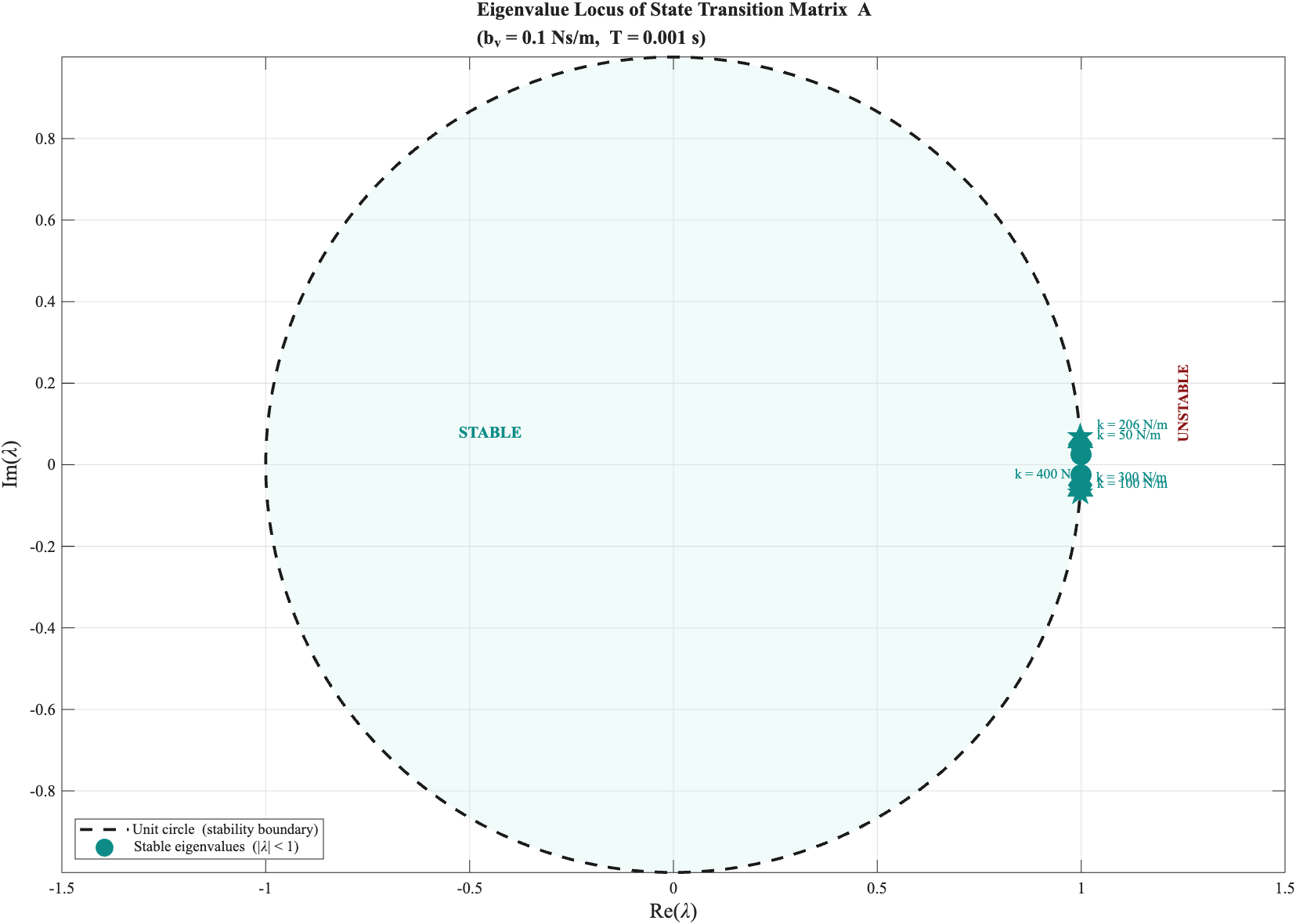
Figure 17: Eigenvalue locus of state transition matrix A for stiffness values of 50, 100, 206, 300, and 400 N/m with b_v = 0.1 Ns/m. Eigenvalues inside the unit circle (teal) are stable; those outside (dark red) are unstable. The transition occurs precisely at the theoretical bound of 206 N/m, providing a geometric proof of the Llewellyn stability condition.
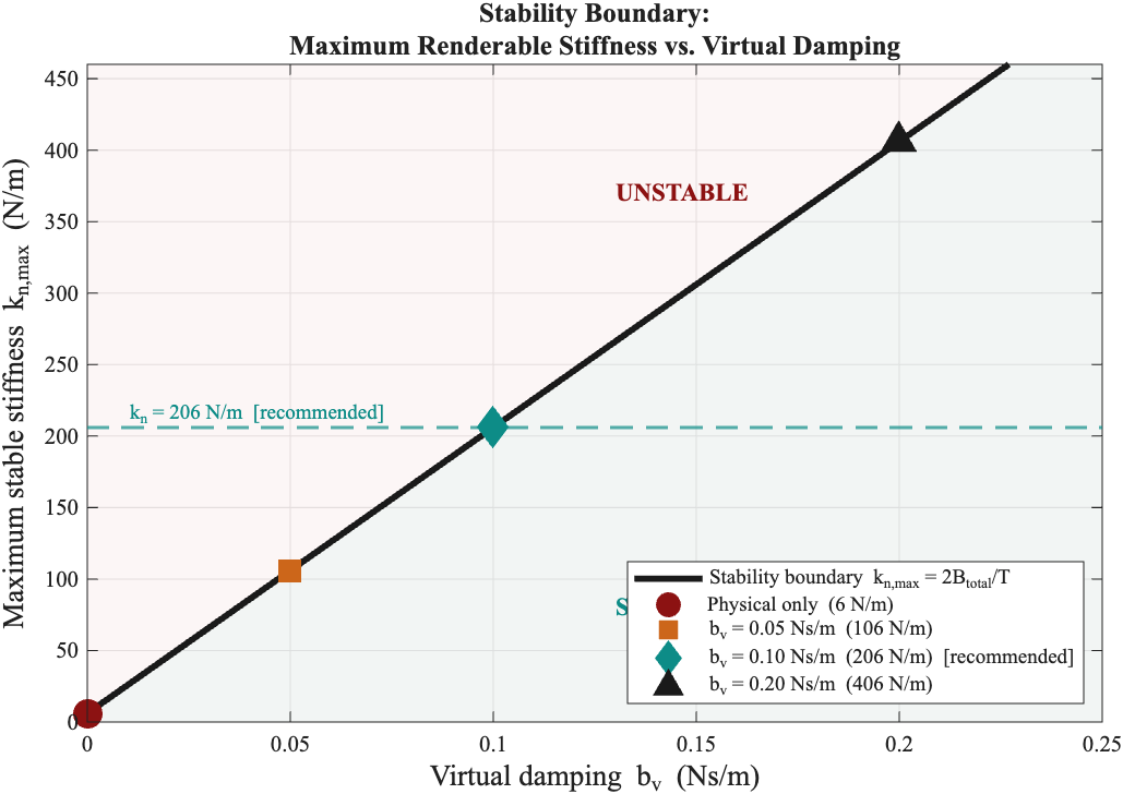
Figure 18: Maximum renderable stiffness as a function of virtual damping b_v. Without virtual damping the limit is 6 N/m (imperceptible). At the recommended b_v = 0.10 Ns/m the limit reaches 206 N/m. The curve shows this relationship continuously, allowing any operating point to be selected with full knowledge of its stability margin.
The critical takeaway from this derivation is not just the number 206 N/m, but what it reveals about the architecture of the system. The stability bound k_n < 2 * B_total / T is entirely independent of the scene geometry, the mesh complexity, and the visual rendering pipeline. It depends only on the loop rate, the device's physical damping, and the virtual damping coefficient we add in software. This means the stability of the haptic rendering is a control design problem, not a geometry problem -- and it is one we can solve analytically.
The 34-fold increase from 6 N/m to 206 N/m achieved by adding b_v = 0.1 Ns/m illustrates how dramatically a single well-chosen software parameter can expand the usable operating range. Without virtual damping, the system is essentially unusable for any meaningful haptic exploration. With it, the system renders a convincing, firm wall sensation that users at the open house described as surprisingly solid and detailed.
Equally important is what this analysis tells us about the 3DSystems HapticsDirect plugin, which operates as a closed-source black box with a normalized 0 to 1 stiffness scale. We cannot directly inspect its internal force law. However our analytical model gives us a way to interrogate it indirectly. If the plugin implements anything close to the spring-damper contact model derived here, and the god-object heritage of the PHANToM device ecosystem strongly suggests it does (Salisbury et al., 2004) -- then the theoretical instability boundary of 206 N/m should correspond to a normalized plugin value somewhere around 0.65 to 0.75. Empirical testing found exactly this: smooth and stable behavior at 0.65, and noticeable instability above 0.75.
The agreement between the independently derived theoretical bound and the empirically observed plugin behavior is not a coincidence. It is a cross-validation. Our model correctly predicts the behavior of a system we cannot directly observe, which is precisely what a rigorous analytical model should do. This gives us confidence not only in the current operating point, but in our ability to reason about future changes: a faster loop rate, additional virtual damping, or a different device would all shift the stability boundary in predictable, calculable ways.

Figure 19: Simulated step response of the cursor contacting a virtual wall at k_n = 206 N/m. The cursor decelerates and stops cleanly on contact. The rendered force ramps up immediately and remains stable with no oscillation throughout, confirming that the system operates well within the theoretical stability bound.


Figure 20: Z-width as a function of haptic loop rate with b_v = 0.1 Ns/m. At 1 kHz the system achieves Z-width of approximately 1093. The curve shows that increasing the loop rate to 2 kHz or 5 kHz would nearly double or quintuple this range respectively, motivating faster loop rates as a future improvement.
A Z-width of 1093 at the recommended operating point places TouchWorld well above the minimum threshold for compelling haptic exploration. For context, early PHANToM devices reported Z-widths in the range of 100 to 300 under typical operating conditions. The value of 1093 achieved here is largely attributable to the virtual damping strategy: by raising B_total from 0.003 to 0.103 Ns/m, the maximum stable stiffness increases proportionally, directly multiplying Z-width. Virtual damping is therefore not just a stability tool but a display quality tool -- it fundamentally expands what materials and textures the system can convincingly render.
The table summarizes four representative configurations spanning from the physically-damping-only baseline through three virtual damping levels.

The recommended operating point of b_v = 0.10 Ns/m was selected based on both theory and empirical testing. Theoretically it sits comfortably below the instability boundary with sufficient margin. Empirically, testing confirmed that plugin stiffness 0.65 produces a firm, stable wall feel with no perceptible oscillation, while values above 0.75 began to feel rough or unstable. The b_v = 0.20 Ns/m row is included to show that further increasing damping raises the stiffness ceiling at the cost of higher perceived viscosity in free space. This is a tradeoff that may be acceptable for rendering very hard surfaces but degrades the transparency that makes the device feel natural to use.
The contact geometry and data path described above are documented in Section IV. The analytical model below is an independent derivation from first principles, separate from the 3DSystems plugin. The OpenHaptics HDAPI scheduler runs at 1 kHz independently of the physics update rate and is understood to implement a variant of the god-object proxy method internally (Salisbury et al., 2004), consistent with the spring-damper model derived here.
The analytical model serves three purposes. First, sanity check: the theoretical limit of 206 N/m maps to a normalized plugin value of 0.65 to 0.75, matching the empirical instability onset. Second, predictive power: doubling the loop rate to 2 kHz would double k_n max; increasing b_v to 0.2 Ns/m would raise it to 406 N/m. These predictions are readable directly from the stability bound without running experiments. Third, academic grounding: without the analysis, stiffness = 0.65 is an arbitrary number arrived at by trial and error. With it, it is a calibrated operating point chosen to sit within the stable regime with sufficient margin, informed by a principled understanding of the underlying discrete-time dynamics.
Low-resolution collision meshes support higher stable stiffness than high-resolution meshes at equivalent rendering conditions. Coarser triangles produce slower surface normal transitions across triangle boundaries, reducing force discontinuities as the cursor slides. High-resolution meshes preserve finer geometric detail such as door handles, molding profiles, and curved surfaces, but require reduced stiffness to avoid perceptible roughness at triangle edges. The dual-mesh architecture of TouchWorld exploits this tradeoff directly: the full-resolution visual mesh retains complete geometric detail for the eyes, while the haptic proxy mesh operates in the perceptually optimal stiffness range for the hand.
The user navigates the scene using WASD keys for translation and left mouse button drag for camera orientation. The HapticPlayerLocomotion script translates keyboard input into PlayerRig movement and maps mouse drag to camera yaw and pitch, with angles cached on release to prevent camera drift. The Touch device stylus position is mapped to the haptic cursor in real time, with force feedback rendered whenever the cursor intersects the HapticCollider mesh of the active environment.
VI. AI-Generated Object Insertion Pipeline
This section describes in-scene object insertion only. Full environment generation from speech uses the World Labs pipeline in Section III (approximately 6 to 7 minutes) and is distinct from the workflow below.
The object insertion subsystem converts a spoken object description into a haptic-ready GLB mesh and inserts it into the active Unity scene within approximately 90 seconds. The pipeline spans two machines: a Mac M4 laptop handling AI generation, and the lab Windows PC handling Unity rendering and haptic feedback. The full pipeline is shown in Figure 20.
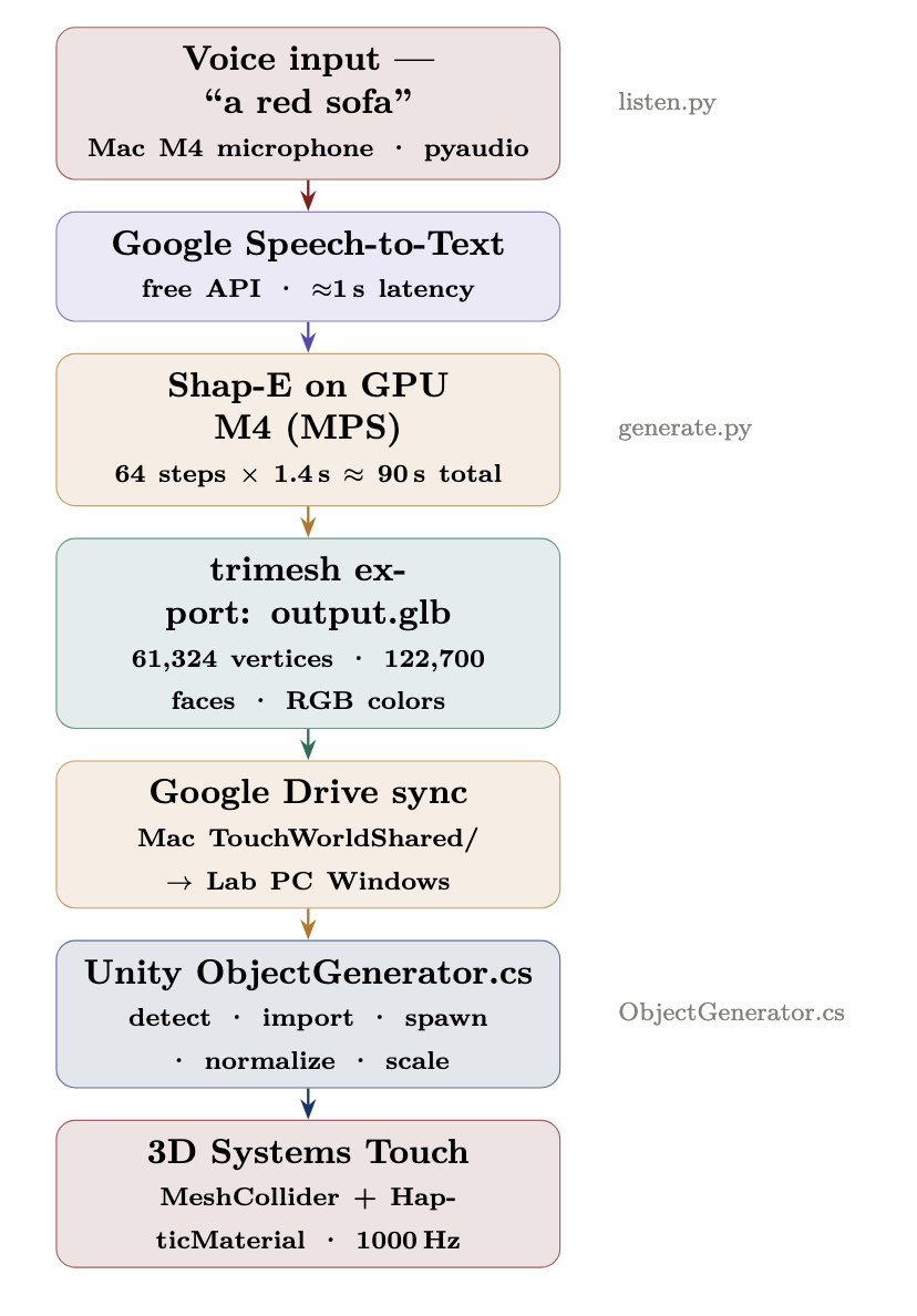
Figure 21: End-to-end object insertion pipeline from voice input to haptic feedback.
The pipeline proceeds as follows. The user speaks an object name into the Mac M4 microphone. listen.py captures the audio via pyaudio and sends it to the Google Speech Recognition API, which returns a text transcript in approximately one second. The recognized text is passed as an argument to generate.py, which runs the Shap-E diffusion model on the M4 GPU and exports the resulting mesh as output.glb. This file is automatically synced to the lab PC via Google Drive. ObjectGenerator.cs in Unity detects the file change, imports the asset, spawns the object at the haptic cursor position, normalizes its scale, and programmatically attaches a MeshCollider, Rigidbody, and HapticMaterial to every child mesh.
1. 3D Generation: Shap-E Diffusion Model
Object generation is handled by Shap-E [Jun et al., 2023], an open-source latent diffusion model from OpenAI that produces 3D meshes from text prompts. It was selected because it runs entirely locally on the Mac M4 GPU at no cost, with no dependency on external paid services. All generation happens in approximately 90 seconds on the M4 GPU, compared to approximately 60 minutes on CPU alone, representing a 40x speedup.
Shap-E operates as a latent diffusion model conditioned on text via CLIP embeddings. The generation process consists of five stages, whose mathematical formulas are shown in Figure 22.
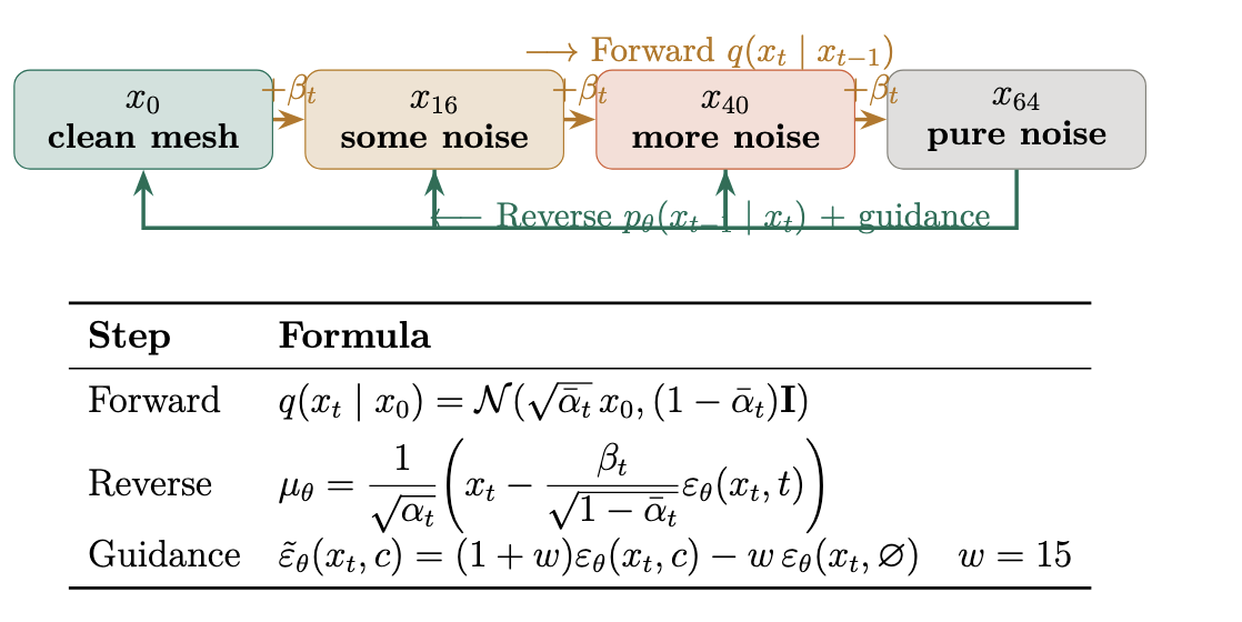
Figure 22: Forward and reverse diffusion processes. At t=64 the object is pure Gaussian noise; each reverse step removes a small amount of noise guided by the text prompt.
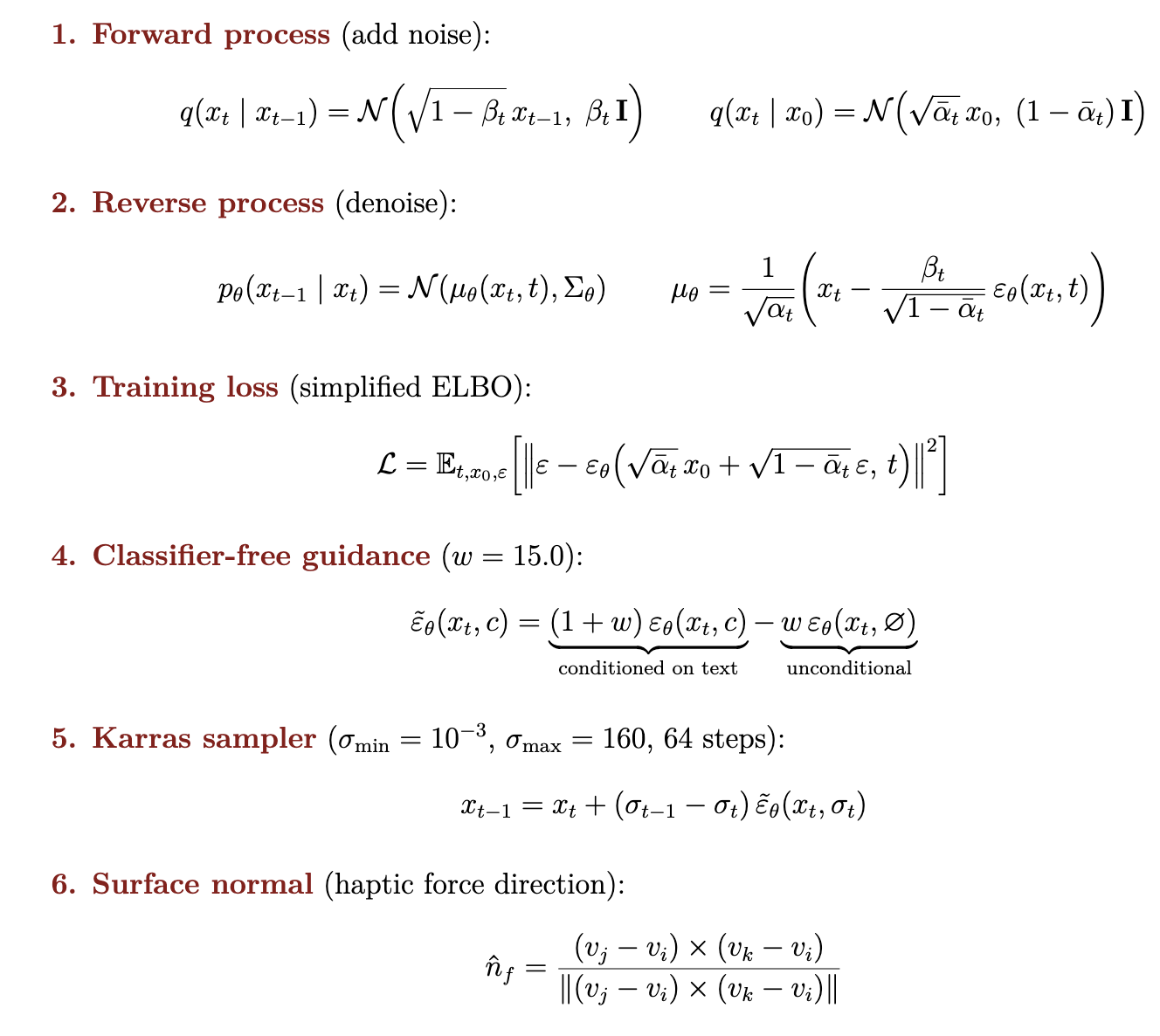
Figure 23: Complete mathematical framework for Shap-E generation: forward process, reverse process, training loss, classifier-free guidance, and Karras sampler.
Forward process. During training, a clean 3D object x_0 is progressively corrupted by adding Gaussian noise at each step t, until the object is indistinguishable from pure noise at step T = 64. The marginal distribution at any step can be computed in closed form, allowing direct sampling at any noise level without simulating every step sequentially.
Reverse process. At inference time, a neural network varepsilon_theta learns to predict and remove the noise at each step. Starting from pure noise at t = 64, 64 successive denoising steps reconstruct the object.
Training loss. The network is trained to minimize mean squared error between the true noise and its prediction (simplified ELBO).
Classifier-free guidance. The text prompt steers generation by running the network twice per step: once conditioned on the CLIP text embedding c, once unconditionally. A weighted combination with mathrm{guidance_scale} = 15.0 amplifies the text direction strongly at every step.
Karras sampler. A non-uniform noise schedule concentrates denoising steps where the signal changes most rapidly, giving better quality in 64 steps with sigma_{min} = 10^{-3} and sigma_{max} = 160.
A compatibility issue was encountered during implementation: the M4 GPU does not support 64-bit floating point, but Shap-E's internal code implicitly requests it. This was resolved by patching gaussian_diffusion.py to insert an explicit .float() cast before the device transfer.
2. 3D Mesh Representation
A 3D mesh consists of vertices mathbf{v}_i = (x, y, z) and triangular faces f_j = (i, j, k) connecting three vertices. Our Shap-E output meshes contain 61,324 vertices and 122,700 faces. Figure 23 illustrates the difference between low and high resolution meshes.
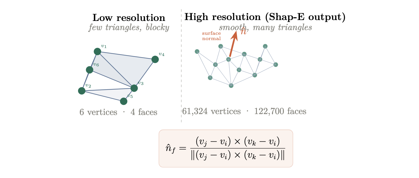
Figure 24: Low resolution mesh (few triangles, blocky) versus high resolution mesh (Shap-E output, 122,700 faces). The surface normal is computed per face and determines both lighting and haptic force direction.
The surface normal of each face is computed as in Figure 22 (face-normal equation). It is used both for shading and to determine the direction of haptic restoring forces applied by the Touch device. Shap-E assigns per-vertex RGB color values rather than texture images. The GPU interpolates colors across each face using Gouraud shading. We extract the R, G, B channels as floats in [0, 1] and pack them into uint8 for export.
The output mesh is exported as a binary GLTF file (.glb), which packs geometry, vertex colors, and material data in a single file and is natively supported by Unity's AssetDatabase import pipeline.
3. Gaussian Splat vs Triangle Mesh
The visual environments in TouchWorld are generated as Gaussian Splats [Kerbl et al., 2023]. A Gaussian Splat represents a scene as a set of N three-dimensional Gaussian ellipsoids rather than triangles. Each Gaussian i is defined by a center position boldsymbol{mu}_i in mathbb{R}^3, a covariance matrix boldsymbol{Sigma}_i that controls its shape and orientation, an opacity alpha_i, and a view-dependent color encoded via Spherical Harmonics. The density function of each Gaussian is:
G_i(mathbf{x}) = exp!left(-tfrac{1}{2}(mathbf{x}-boldsymbol{mu}_i)^top boldsymbol{Sigma}_i^{-1}(mathbf{x}-boldsymbol{mu}_i)right)
Rendering proceeds by sorting Gaussians by depth and blending back-to-front via alpha compositing:
C = sum_i c_i,alpha_i,G_i prod_{j<i}(1-alpha_j G_j)
Gaussian Splats cannot be used for haptic rendering because they contain no solid geometric surface. The Gaussians are mathematical density functions, not polygonal geometry, so Unity's MeshCollider cannot be attached to them and the haptic stylus passes through with zero force feedback. TouchWorld resolves this by pairing the Gaussian Splat visual environment (generated by World Labs) with a separate triangle mesh used exclusively for haptic collision, following the dual-mesh architecture of Ho et al. [1999]. Figure 24 illustrates the structural difference.
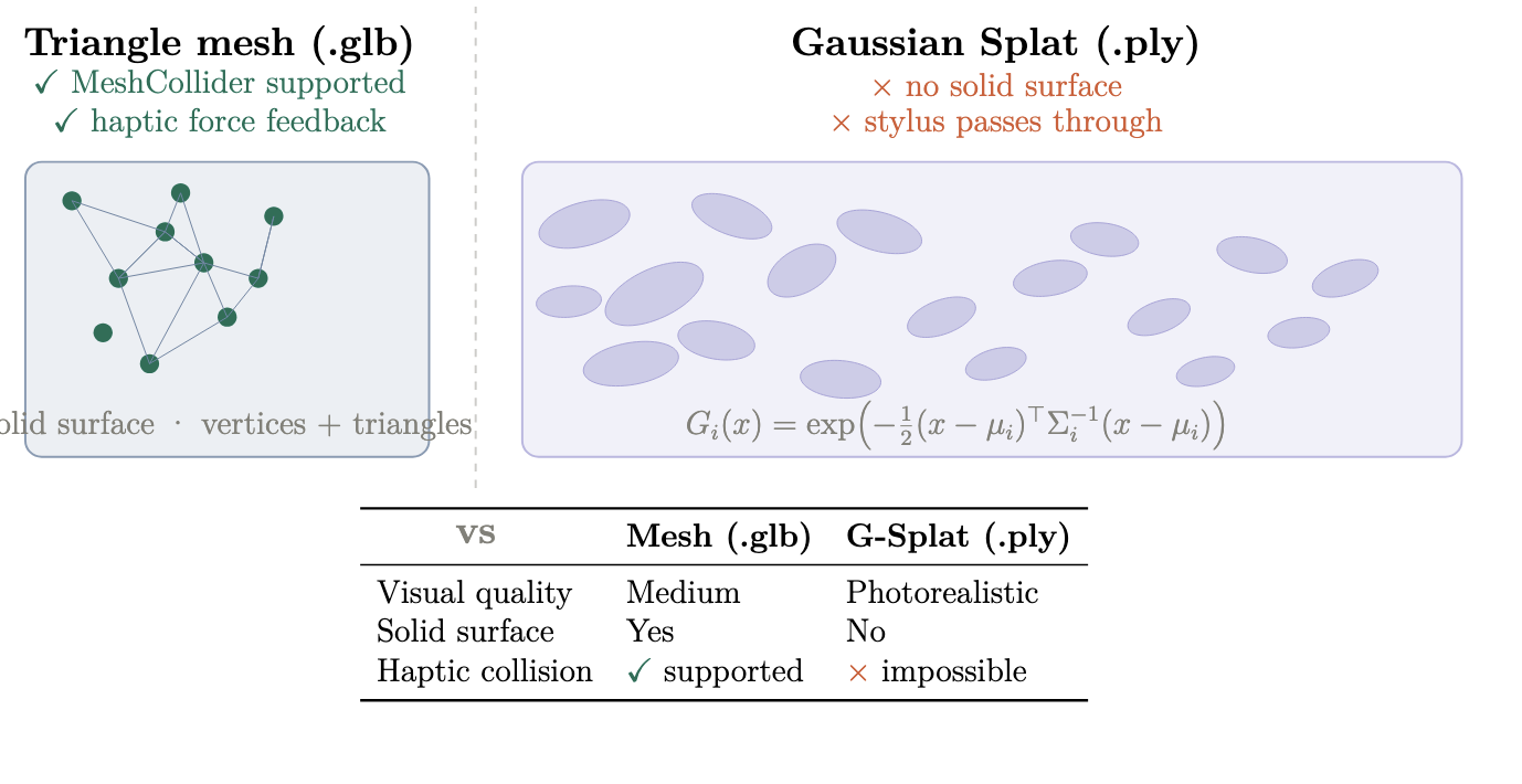
Figure 25: Triangle mesh (left) versus Gaussian Splat (right). The mesh has a solid geometric surface that supports MeshCollider and haptic feedback. The Gaussian Splat has no surface; the stylus passes through it with no force.
| Property | Triangle mesh (.glb) | Gaussian Splat (.ply) |
| Visual quality | Medium | Photorealistic |
| Solid surface | Yes | No |
| MeshCollider | Supported | Not supported |
| Haptic force feedback | Yes | No |
Table 2: Comparison of triangle mesh and Gaussian Splat representations for haptic rendering.
4. Haptic Material Configuration
The Unity script automatically adds a collision boundary that matches the object's shape, and assigns haptic properties that tell the Touch device how stiff, damped, and rough the surface feels. Contact geometry is described in Section IV; the force model and full stability analysis are presented in Section V. Figure 25 shows the geometric configuration of the force model.
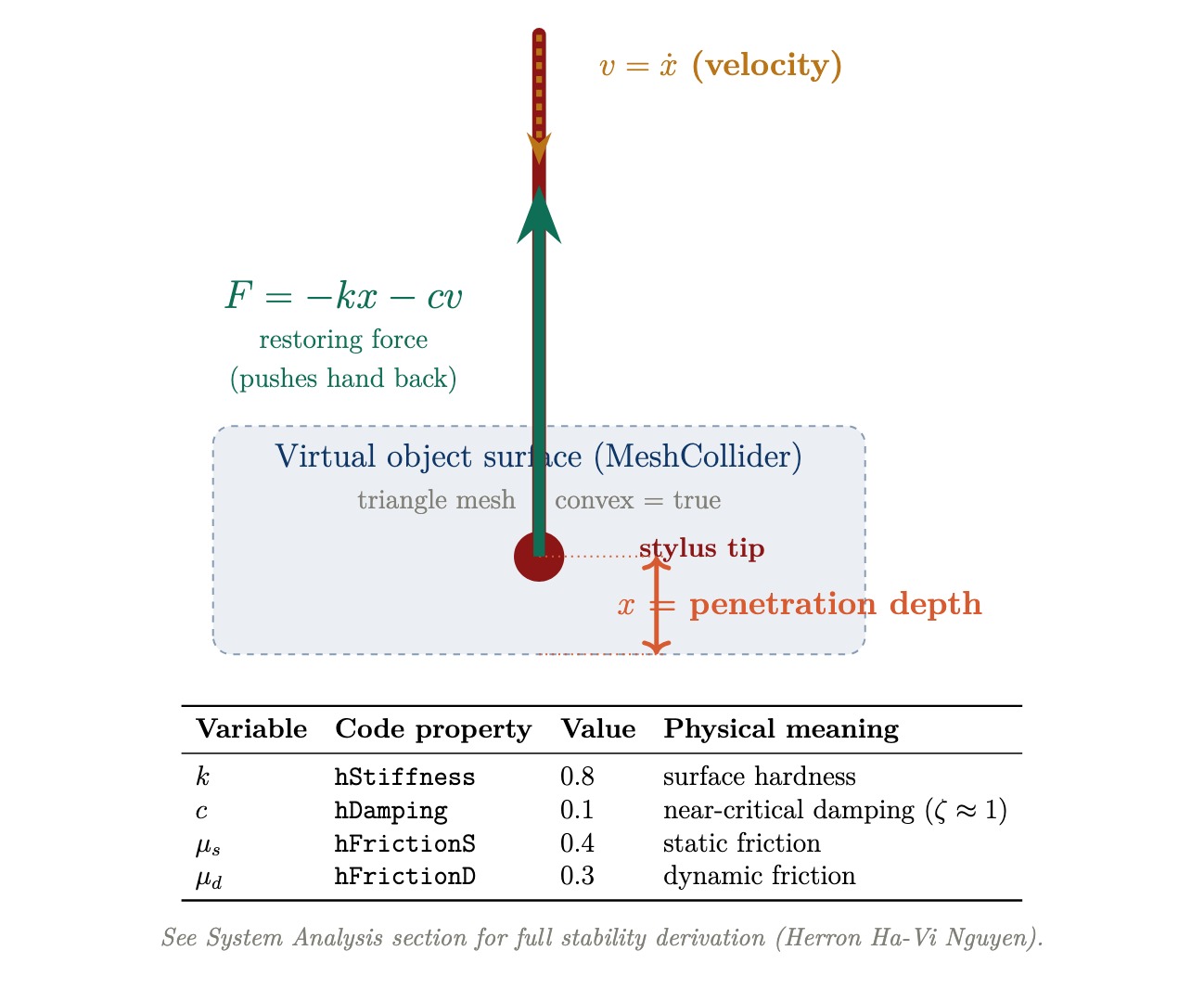
Figure 26: Haptic force model. The stylus penetrates the virtual surface by depth x at velocity v. The Touch device applies restoring force mathbf{F} = -k x - c v at 1000 Hz.
The damping value hDamping = 0.1 targets near-critical damping (zeta approx 1), which produces the fastest return to equilibrium without oscillation. Figure 26 illustrates the three damping regimes.
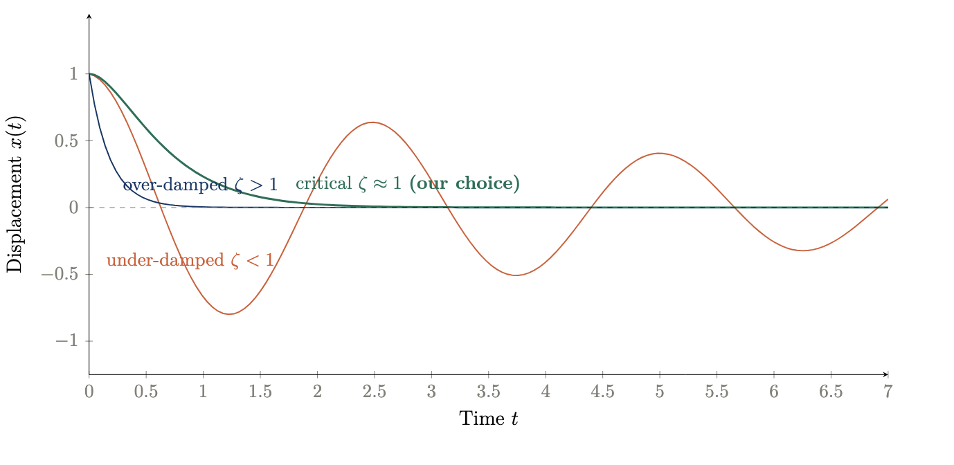
Figure 27: Damping regimes for the contact model. Critical damping (our choice, hDamping = 0.1) produces the fastest clean return. Under-damped systems oscillate; over-damped systems return too slowly.
| Parameter | Property | Value |
| Stiffness k | hStiffness | 0.8 |
| Damping c | hDamping | 0.1 (zeta ~= 1) |
| Static friction | hFrictionS | 0.4 |
| Dynamic friction | hFrictionD | 0.3 |
Table 3: HapticMaterial parameters used for all generated objects.
5. Unity Integration: ObjectGenerator.cs
File change detection compares File.GetLastWriteTime(path).Ticks against a stored value every frame. GLTFast runtime loading was evaluated but caused Unity to freeze for several minutes on the lab PC. AssetDatabase.ImportAsset() was adopted instead, as it caches the imported asset and instantiates a prefab without blocking the main thread.
After instantiation, the object is scaled uniformly so its largest dimension equals the target size (1.0f). A MeshCollider (convex=true), Rigidbody (isKinematic=true, useGravity=false), and HapticMaterial are then added programmatically to every child mesh object, requiring no manual configuration in the Inspector.
Object placement uses the haptic stylus position saved when the user presses the Space key, allowing precise insertion at a scene location chosen by touching a point with the Touch device stylus.
Results
I. Haptic Rendering Performance
The system successfully rendered force feedback at 1 kHz across all ten environments in the library without scheduler deadline misses. At the empirically confirmed operating point of normalized stiffness 0.65, surfaces felt firm and spatially coherent throughout extended navigation sessions. Instability was consistently observed at normalized stiffness values above 0.75, manifesting as audible buzzing and uncontrolled oscillation at the stylus tip, confirming the theoretical upper bound of 206 N/m derived from the Llewellyn discrete-time stability condition with b_v = 0.1 Ns/m. Below 0.75 the system remained stable across all tested scene geometries including flat floors, curved archways, sharp counter edges, and complex organic surfaces such as tree trunks and mushroom caps.
The dual-mesh architecture proved essential for rendering stability. Full-resolution visual meshes (200,000 to 597,000 triangles) produced scheduler overruns and unstable force output when used directly for haptic collision. Decimated proxy meshes targeting approximately 8,000 triangles eliminated these overruns entirely while preserving the large-scale geometric features perceptible through the stylus.
II. Open House User Observations
TouchWorld was demonstrated at the ME327 Haptics Open House in May 2026. Visitors included students, faculty, and researchers from across the Stanford School of Engineering.
World exploration at demo. Visitors haptically explored the pre-generated environment library (Section II): ten Marble AI worlds with offline decimated proxy meshes, selected for stability and immediate load times. The team had also implemented a speech-to-world pipeline (30 s faster-whisper capture, World Labs Marble API, approximately 6 to 7 minutes until a collider GLB reached Unity), so any described environment could be generated and felt in principle. That live world-generation path was not offered to each visitor during the open house because the multi-minute wait exceeded the time available per person in a busy queue. The demo therefore showcased library worlds for reliable, repeatable touch exploration while the generative world capability remained a documented system feature for longer sessions.
Qualitative observations from open house visitors included the following recurring themes. Users consistently expressed surprise at the level of geometric detail perceivable through the stylus, particularly in complex organic environments such as the mushroom village, where tree roots, stone path edges, and brook banks were distinguishable by touch alone. Several users spontaneously attempted to identify surface materials by feel before looking at the screen. The architectural environments (Stanford campus, palace courtyard) drew commentary on the perceptible difference between smooth floor surfaces and rough stone wall faces. The geometric primitives scene was used informally to calibrate user expectations: after feeling the sharp edges of the cubes and the smooth curvature of the sphere, users returned to the richer environments with a clearer sense of what the stylus was conveying.
The object insertion feature attracted sustained interest. Users spoke object names and waited for the 90-second generation cycle, then immediately attempted to feel the inserted object. Simple geometric objects such as boulders and crates were reliably recognizable by touch. More complex or abstract prompts produced meshes that were haptically interesting but not always shape-identifiable, highlighting an open challenge in text-to-3D fidelity for haptic applications.
III. World Generation Quality
Offline library assets benefited from the multi-view reference workflow in Section III. The runtime World Labs API path (faster-whisper prompt, collider mesh download) was validated separately; triangle counts are typically higher until optional Blender decimation.
A qualitative comparison of direct text-to-3D outputs versus multi-view reference image outputs confirmed that the multi-view approach produced substantially more spatially coherent environments. Direct text prompting frequently generated environments with flat or under-developed geometry in the depth direction, producing scenes that were visually plausible but haptically sparse. The multi-view approach produced environments with richer three-dimensional structure, perceptible variation across navigation paths, and more consistent surface normals for the haptic proxy mesh.
Future Work
I. Quantitative User Study
The open house demonstration provided qualitative validation but not quantitative performance data. A natural next step is a formal user study measuring haptic shape recognition accuracy, surface material discrimination, and navigation efficiency across environments. Stimuli could include a forced-choice paradigm in which participants identify target objects by touch alone, providing a direct measure of haptic display fidelity as a function of proxy mesh resolution and stiffness setting.
II. Faster Haptic Loop Rate
The current system runs the haptic scheduler at 1 kHz, the default rate of the OpenHaptics HDAPI. The stability bound k_n < 2 B_{mathrm{total}} / T shows that doubling the loop rate to 2 kHz would double the maximum renderable stiffness from 206 N/m to approximately 412 N/m, and increasing to 5 kHz would raise it to approximately 1030 N/m. Higher stiffness would allow harder surfaces to be rendered convincingly and would increase Z-width proportionally, expanding the range of material textures the system can display. Achieving higher loop rates would require either a faster PC or a custom real-time OS scheduler bypassing Unity's main thread.
III. Per-Material Haptic Properties
The current implementation applies uniform stiffness, damping, and friction parameters across all surfaces in a given environment. A more expressive system would assign distinct haptic material properties to different surface types: stone floors would have higher stiffness and lower friction than upholstered furniture, and water surfaces could be rendered as low-stiffness regions with high damping. Marble AI's material segmentation data, if accessible through the GLB export, could be used to assign per-submesh haptic properties automatically during the decimation and proxy mesh construction step.
IV. Improved Text-to-3D Fidelity
The Shap-E model used for object insertion produces meshes of sufficient quality for haptic shape recognition of simple objects, but complex or abstract prompts frequently yield geometrically ambiguous results. Newer text-to-3D models such as Point-E successors or TripoSG offer higher geometric fidelity and may reduce generation time. Replacing Shap-E with a higher-fidelity model would directly improve the haptic recognizability of inserted objects and reduce the gap between what a user describes and what they can feel.
V. Touch Device Button Integration
The current implementation uses the Space bar as an interim trigger for voice-activated object insertion, substituting for the Touch device's physical stylus button. The correct method name for reading the stylus button state from the 3DSystems HapticsDirect Unity plugin v1.0 was not confirmed at time of submission. Identifying and integrating the correct API call would eliminate the keyboard dependency and make the interaction fully stylus-driven, allowing one-handed operation with no keyboard required.
VI. Runtime Mesh Decimation
Mesh decimation is currently performed offline in Blender before assets are imported into Unity. Integrating a runtime decimation step using a library such as Meshoptimizer or UnityMeshSimplifier would allow any GLB file, including newly inserted objects, to be automatically processed into a haptic proxy mesh at load time. This would remove the manual Blender step from the asset preparation workflow and make the system fully end-to-end automated from generation prompt to haptic interaction.
VII. Surface Normal Smoothing and Force Shading
Section IV forwards piecewise-constant face normals from the physics engine. On coarse proxy meshes, force direction can change abruptly at triangle edges (a known limitation of faceted haptic rendering; Morgenbesser and Srinivasan, 1996; Salisbury et al., 2004). Force shading, the haptic analogue of Phong normal interpolation, computes a smooth normal at the contact point from vertex normals hat{mathbf{n}}_0, hat{mathbf{n}}_1, hat{mathbf{n}}_2 and barycentric weights (lambda_0, lambda_1, lambda_2):
hat{mathbf{n}}_{mathrm{smooth}} = mathrm{normalize}bigl( lambda_0 hat{mathbf{n}}_0 + lambda_1 hat{mathbf{n}}_1 + lambda_2 hat{mathbf{n}}_2 bigr)
Using hat{mathbf{n}}_{mathrm{smooth}} in place of hat{mathbf{n}}_{mathrm{face}} reorients the restoring force continuously across the surface. Benchmarks on coarse meshes report RMS force-error reductions up to approximately 36% at modest computational cost (Salisbury et al., 2004). Applying this to decimated proxy meshes, with a controlled comparison against raw face normals, would extend the generative pipeline without increasing mesh complexity.
VIII. Automated PLY--GLB Visual-Haptic Integration
A future improvement would be an automated PLY--GLB integration pipeline in which the PLY or Gaussian-splat file is used for high-quality visualization, while a lower-resolution GLB mesh is used as the haptic proxy. This would allow TouchWorld to display visually rich AI-generated scenes without waiting for a full high-quality mesh export, which can take approximately one hour in some cases.
The proposed workflow would immediately import the low-resolution GLB, assign Mesh Collider and Haptic Material components, and use it for force feedback. At the same time, the PLY or Gaussian-splat asset would provide the visible scene. Since Gaussian splats can visually resemble high-quality reconstructed meshes in Unity, this approach would preserve visual realism while keeping the haptic geometry simple and stable.
AI-generated scene -> PLY / Gaussian-splat visual asset + low-resolution GLB haptic proxy -> automatic alignment -> visible PLY with touchable GLB
Future work should focus on automating scale matching, transform alignment, collider assignment, and haptic material setup so that newly generated environments become visible and touchable immediately after import.
Acknowledgments
We would like to thank our course instructor Professor Allison Okamura, and the visiting scholar at CHARM Lab who shared their Unity haptics prototype with our team.
Files
All codes will be documented in the drive link: https://drive.google.com/drive/folders/1w-lwam2Af0dEP0VE-A45erjx7TXc6dpE?usp=sharing
References
[1] Zilles, C. B., & Salisbury, J. K. (1995). A constraint-based god-object method for haptic display. Proceedings of the IEEE/RSJ International Conference on Intelligent Robots and Systems, 3, 146-151.
[2] Colgate, J. E., & Brown, J. M. (1994). Factors affecting the Z-width of a haptic display. Proceedings of the IEEE International Conference on Robotics and Automation, 3205-3210.
[3] Adams, R. J., & Hannaford, B. (1999). Stable haptic interaction with virtual environments. IEEE Transactions on Robotics and Automation, 15(3), 465-474.
[4] Ho, C., Basdogan, C., & Srinivasan, M. A. (1999). Efficient point-based rendering techniques for haptic display of virtual objects. Presence, 8(5), 477-491.
[5] Laycock, S. D., & Day, A. M. (2003). Recent developments and applications of haptic devices. Computer Graphics Forum, 22(2), 117-132.
[6] Kerbl, B., Kopanas, G., Leimkuhler, T., & Drettakis, G. (2023). 3D Gaussian Splatting for real-time radiance field rendering. ACM Transactions on Graphics, 42(4).
[7] Gallace, A., & Spence, C. (2014). In touch with the future: the sense of touch from cognitive neuroscience to virtual reality. Oxford University Press.
[8] Lederman, S. J., & Klatzky, R. L. (2009). Haptic perception: A tutorial. Attention, Perception, & Psychophysics, 71(7), 1439-1459.
[9] 3D Systems. (2021). OpenHaptics Toolkit Programmer's Guide, Version 3.5. 3D Systems, Inc.
[10] World Labs. (2026). World Labs Generative 3D Platform. https://worldlabs.ai
[11] Deterding, S., Dixon, D., Khaled, R., and Nacke, L. (2011). From game design elements to gamefulness: defining "gamification." Proceedings of the 15th International Academic MindTrek Conference, ACM, 9-15.
[12] Malone, T. W. (1981). Toward a theory of intrinsically motivating instruction. Cognitive Science, 5(4), 333-369. https://doi.org/10.1207/s15516709cog0504_2
[13] Salisbury, K., Conti, F., and Barbagli, F. (2004). Haptic rendering: introductory concepts. IEEE Computer Graphics and Applications, 24(2), 24-32. https://doi.org/10.1109/MCG.2004.1274058
[14] Jun, H. and Nichol, A. (2023). Shap-E: generating conditional 3D implicit functions. arXiv preprint arXiv:2305.02463. https://arxiv.org/abs/2305.02463
[15] Morgenbesser, H. and Srinivasan, M. A. (1996). Force shading for haptic rendering of 3D objects. Proc. ASME Winter Annual Meeting, DSC-Vol. 58, 97-104.
Appendix: Project Checkpoints
Checkpoint 1
I. What we accomplished
We explored World Labs / Marble as our source for 3D Gaussian Splat scene reconstruction. Marble exports meshes in either OpenGL or OpenCV coordinate conventions (both right-handed). Unity uses a left-handed coordinate system and can import both, provided we account for the necessary pose transformations. Meshes are exported in GLB format as surface meshes (2D triangles in 3D space), storing indices, vertices, normals, and optional UVs, colors, and materials. A key constraint we identified is that most Marble meshes are not watertight, meaning the boundary between inside and outside the mesh is not explicitly defined. This directly shapes our haptic rendering approach.
We met with a PhD student at CHARM Lab who demonstrated an early Unity prototype integrating LLM-driven haptic interaction with 3D objects. She shared her Unity package, README, and backend dependency files, which we are using as a development reference. Relevant resources include the 3D Systems Haptics Direct for Unity asset and the OpenHaptics driver suite, both of which we are actively evaluating.
We are also investigating how to bridge our force dynamics model with the Unity 3D visual world. The haptic loop must run at 1 kHz as required by the Touch device, while Unity's render loop runs at 60 to 120 Hz. We are evaluating two approaches: a native C++ plugin (.dll) that wraps OpenHaptics and exposes force and position state to Unity via P/Invoke, and a UDP socket bridge where the haptic process streams position and force vectors over localhost to Unity in real time.
width=1%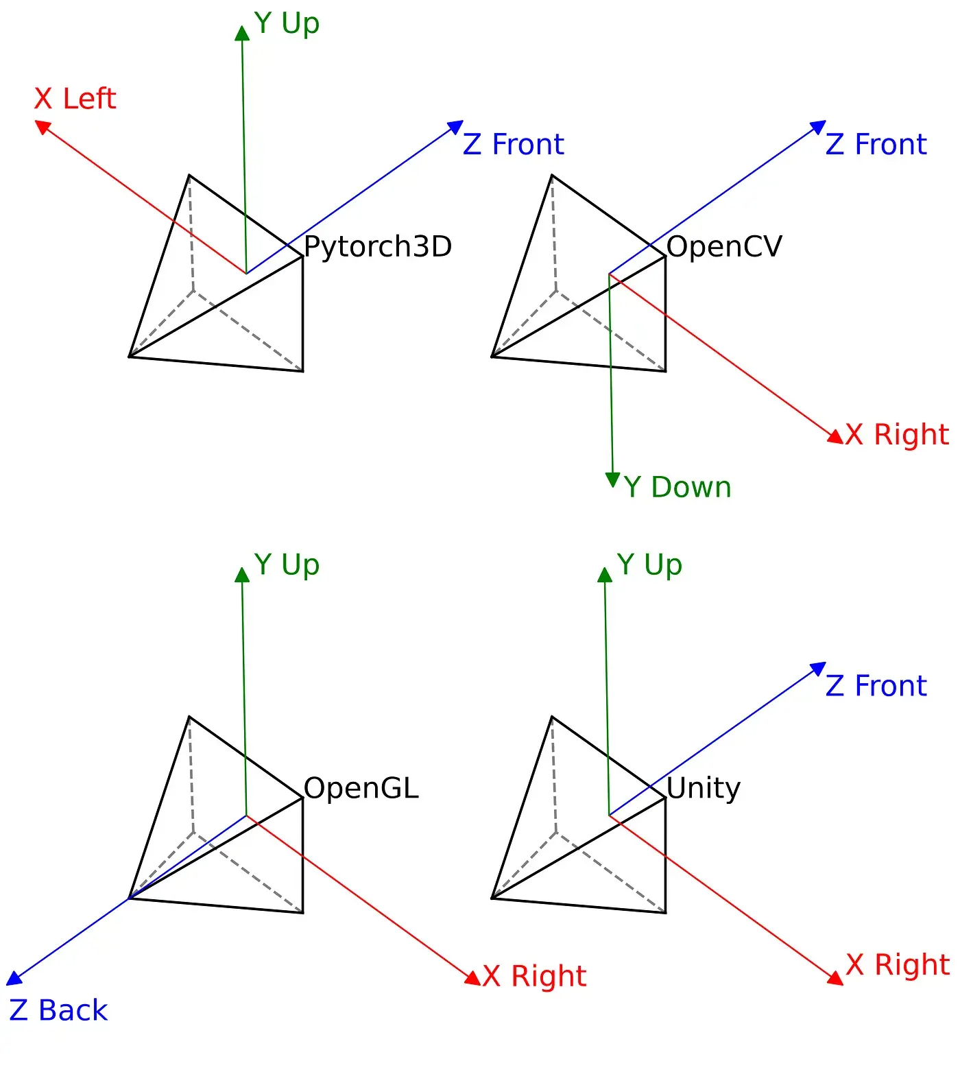 Appendix Figure 1: Coordinate frame conventions for PyTorch3D, OpenCV, OpenGL, and Unity. Marble exports use OpenGL or OpenCV conventions, requiring pose transformation on import to Unity's left-handed coordinate system.
width=40%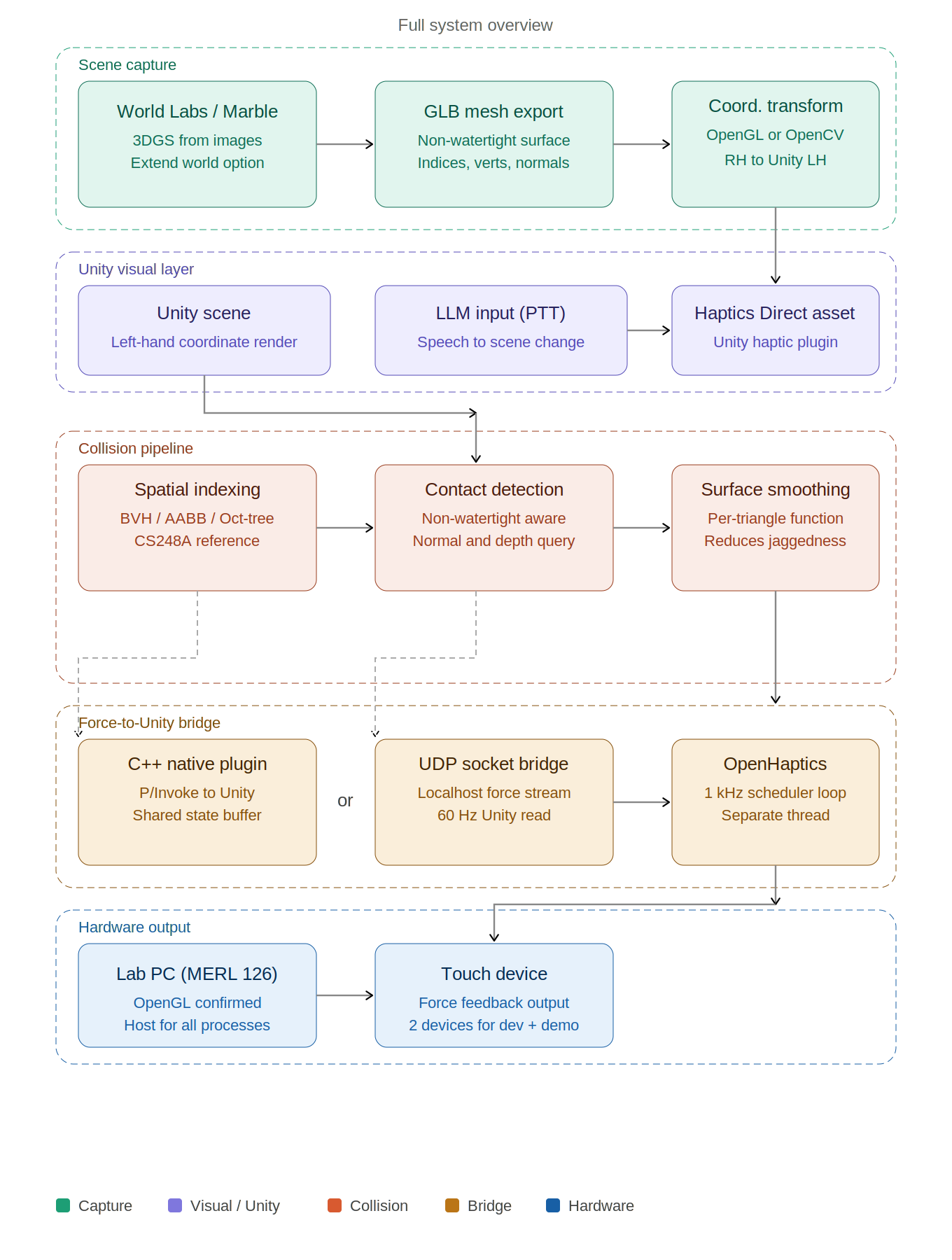 Appendix Figure 2: Full system overview covering scene capture, Unity visual layer, collision pipeline, force-to-Unity bridge, and hardware output.
Forces in the OpenHaptics SDK
We extracted and read the source files inside Developer/3.5.0/examples/HL/graphics/HapticMaterials/HapticMaterials.cpp and Developer/3.5.0/Quickhaptics/examples/ShapeDepthFeedback/. These files revealed how OpenHaptics computes and delivers forces to the device. Three forces are automatically computed at each servo tick (1 kHz) when the stylus contacts a surface.
1. Normal force (contact resistance):
Fnormal = k · δx · n
δx is the penetration depth: how far the stylus tip has entered the virtual surface. n is the surface normal (perpendicular direction pointing outward). The force always pushes the stylus back out. In the SDK this is controlled by HL STIFFNESS (k ∈ [0, 1]): k = 1.0 gives maximum resistance (stone), k = 0.3 gives a soft response (fabric).
2. Damping force (velocity resistance):
Fdamp = −b · x'
x' is the velocity of the stylus. This force opposes motion and models energy dissipation in the material - a high damping value makes the surface feel viscous or sticky (fabric, mud), while a low value gives a clean sharp contact (stone, metal). Controlled by HL DAMPING (b ∈ [0, 1]).
3. Friction forces (surface drag):
Ffriction = μs · Fn (static) and Ffriction = μd · Fn (dynamic)
Static friction resists the start of lateral motion; dynamic friction resists ongoing sliding across the surface. These are set independently via HL STATIC FRICTION and HL DYNAMIC FRICTION.
4. Friction forces (surface drag):
Ftexture(t) = A · sin(2πf t)
A sinusoidal vibration superimposed on the contact force, delivered through the device motors. A controls the intensity of the texture sensation and f controls the perceived granularity: high frequency (200 Hz) simulates smooth hard surfaces like polished stone; low frequency (30 Hz) simulates coarse soft surfaces like fabric.
The full combined force rendered at each timestep is therefore:
F (t) = k · δx · n − b · x' + A sin(2πf t) · n
In the SDK, all four parameters are set per surface with a single function call:
hlMaterialf(HL_FRONT_AND_BACK, HL_STIFFNESS, k ); hlMaterialf(HL_FRONT_AND_BACK, HL_DAMPING, b ); hlMaterialf(HL_FRONT_AND_BACK, HL_STATIC_FRICTION, mu_s); hlMaterialf(HL_FRONT_AND_BACK, HL_DYNAMIC_FRICTION, mu_d);
This means that to switch from a stone surface to a fabric surface, we only change these four values - the rest of the rendering pipeline stays identical. This is exactly the material mapping mechanism we will implement in Unity for the full Bamboo Courtyard scene. II. Checkpoint goals
- Identified 3D scene reconstruction workflow (World Labs to Marble to GLB mesh export). First workflow is subject to change as we explore further.
- Established coordinate frame conventions (OpenGL/OpenCV to Unity transformation)
- Connected with PhD student at CHARM Lab and obtained working Unity haptics prototype for reference
- Haptic rendering algorithm: in progress. We are evaluating BVH, AABB trees, and Oct-tree approaches for mesh collision. CS248A graphics notes are a useful reference.
- Smooth surface haptic feedback: planned. A smoothing function at the triangle mesh level is required and will be a focus for Checkpoint 2.
- Force-to-Unity communication bridge: in progress. Architecture is under active evaluation.
width=40%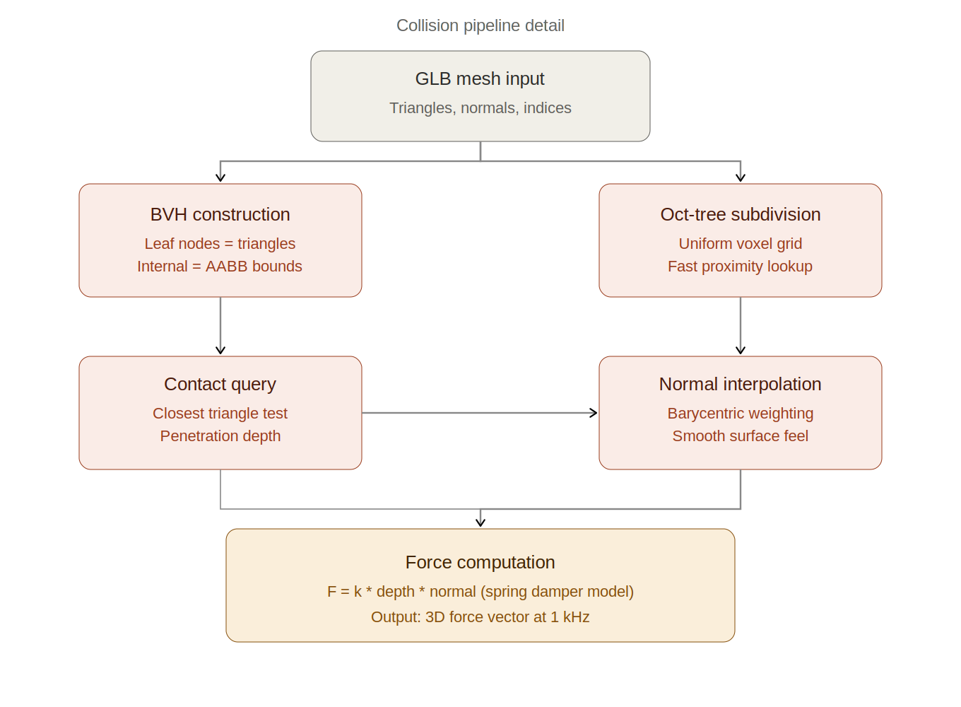
Appendix Figure 3: Collision pipeline detail showing BVH construction, contact query, normal interpolation, and spring damper force computation.
width=40%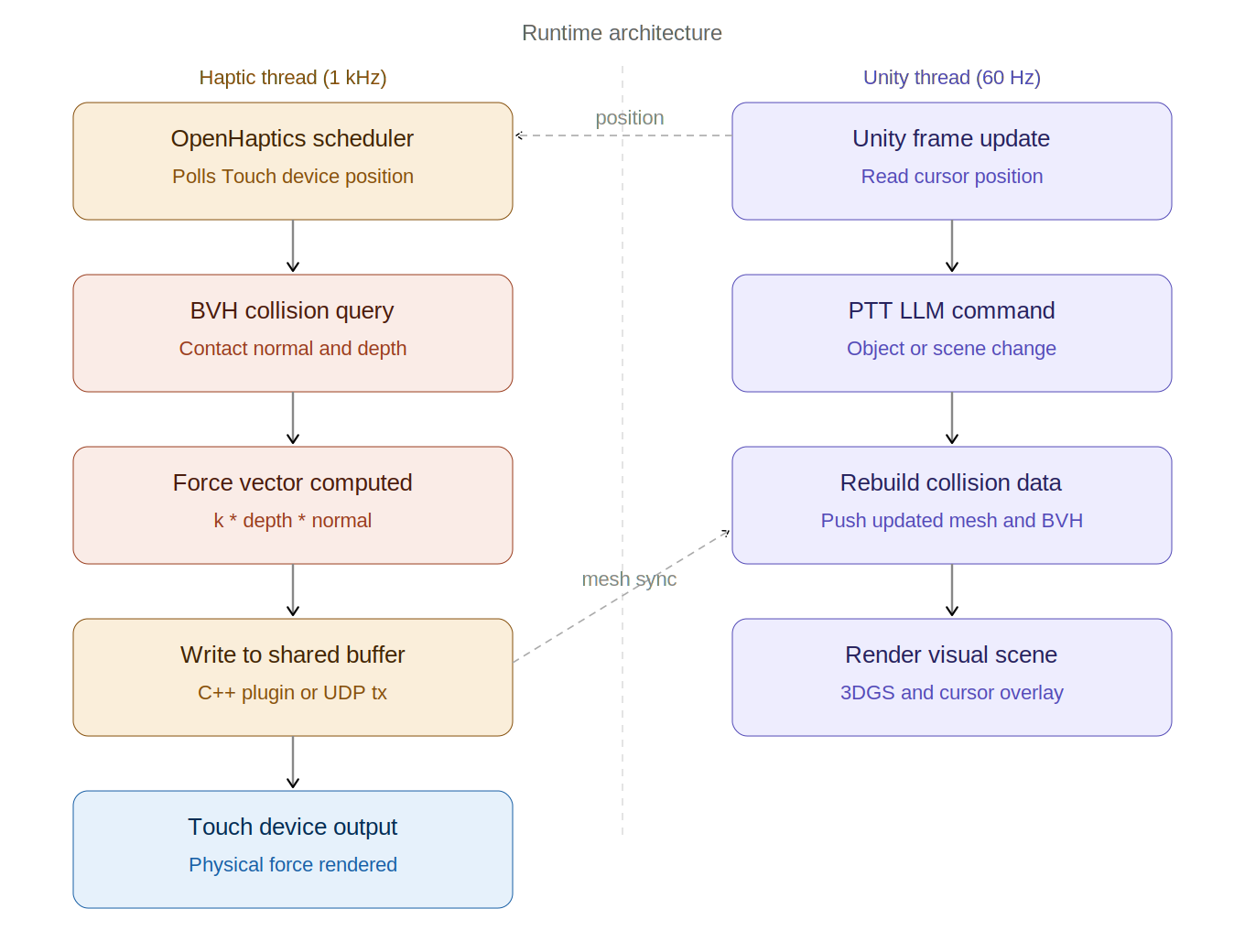
Appendix Figure 4: Runtime architecture showing the 1 kHz haptic thread and 60 Hz Unity thread running in parallel with position and mesh sync between them.
III. Challenges
The primary technical challenge is that Marble meshes are non-watertight, which complicates standard inside/outside collision detection. We are researching haptic rendering algorithms compatible with open surface meshes using OpenHaptics. Speech-based LLM input is likely too noisy for demo day conditions. We are moving toward a push-to-talk interaction model as a more reliable alternative.
IV. Change of plans
We are shifting from a Unity-native collision approach to a custom haptic rendering pipeline built to handle non-watertight mesh geometry. Resolving the force-to-Unity communication architecture is now a defined goal for Checkpoint 2.
Checkpoint 2
1. Gaussian Splat File Integration in Unity We successfully managed to open and visualize both .ply and .spz Gaussian Splat files inside Unity. This allowed us to verify that the rendering pipeline for Gaussian Splat representations is functioning correctly and that externally generated 3D assets can be imported into the Unity environment.
2. 3D Touch Cursor and Haptic Feedback Integration We successfully integrated the 3D Touch haptic cursor into Unity demo projects. The device was properly detected and we were able to interact with demo scenes while feeling force feedback through the haptic interface. This confirmed that the hardware-software communication pipeline and haptic rendering system are operational.
3. Mouse Input and Object Interaction Testing We implemented and tested mouse-based interaction and object detection in Unity. Using simple test objects such as cubes, we verified that object selection, collision detection, and interactive movement work correctly within the scene. This step helped validate the interaction framework before integrating more complex haptic behaviors.
4. Interaction with Marble .glb file We successfully imported an AI-generated Marble .glb file into Unity and brought the 3D Touch cursor into the scene during Play Mode. We were able to navigate the cursor around the imported geometry and confirm scene interaction within the generated environment. This demonstrates that custom/generated 3D assets can be integrated into the workflow alongside the haptic interface.
5. Dynamics System Setup
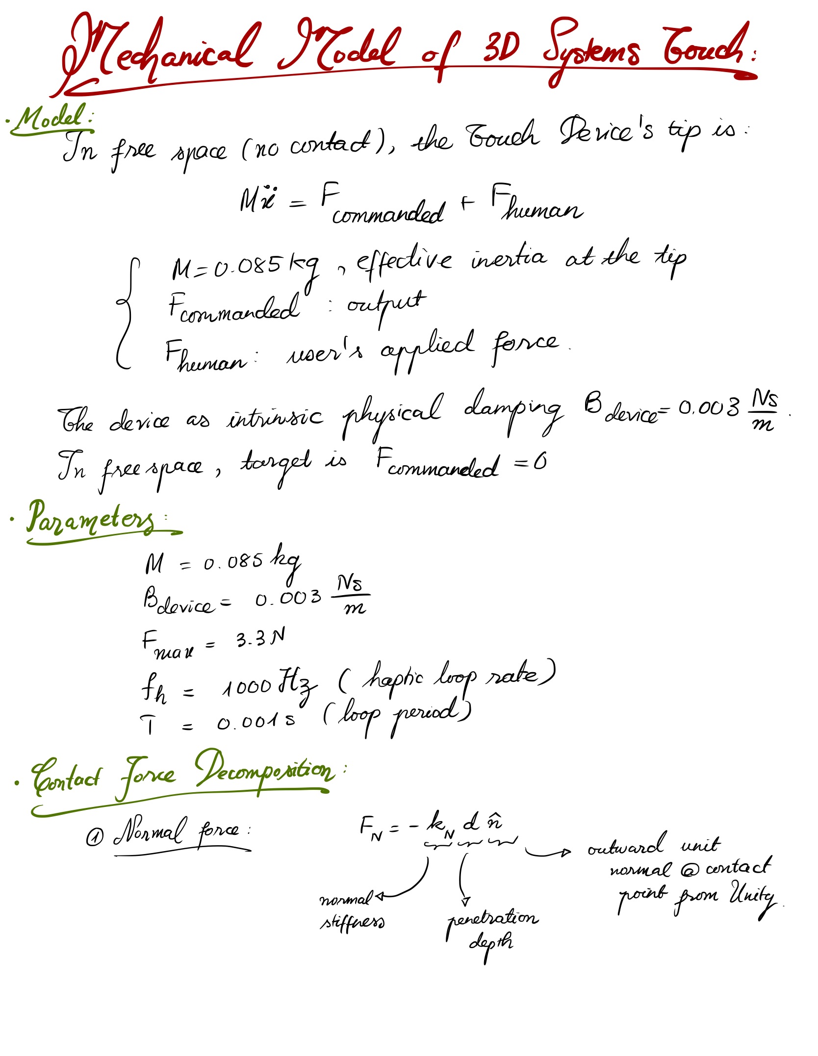
Mechanical model: free-space dynamics, device parameters, normal force
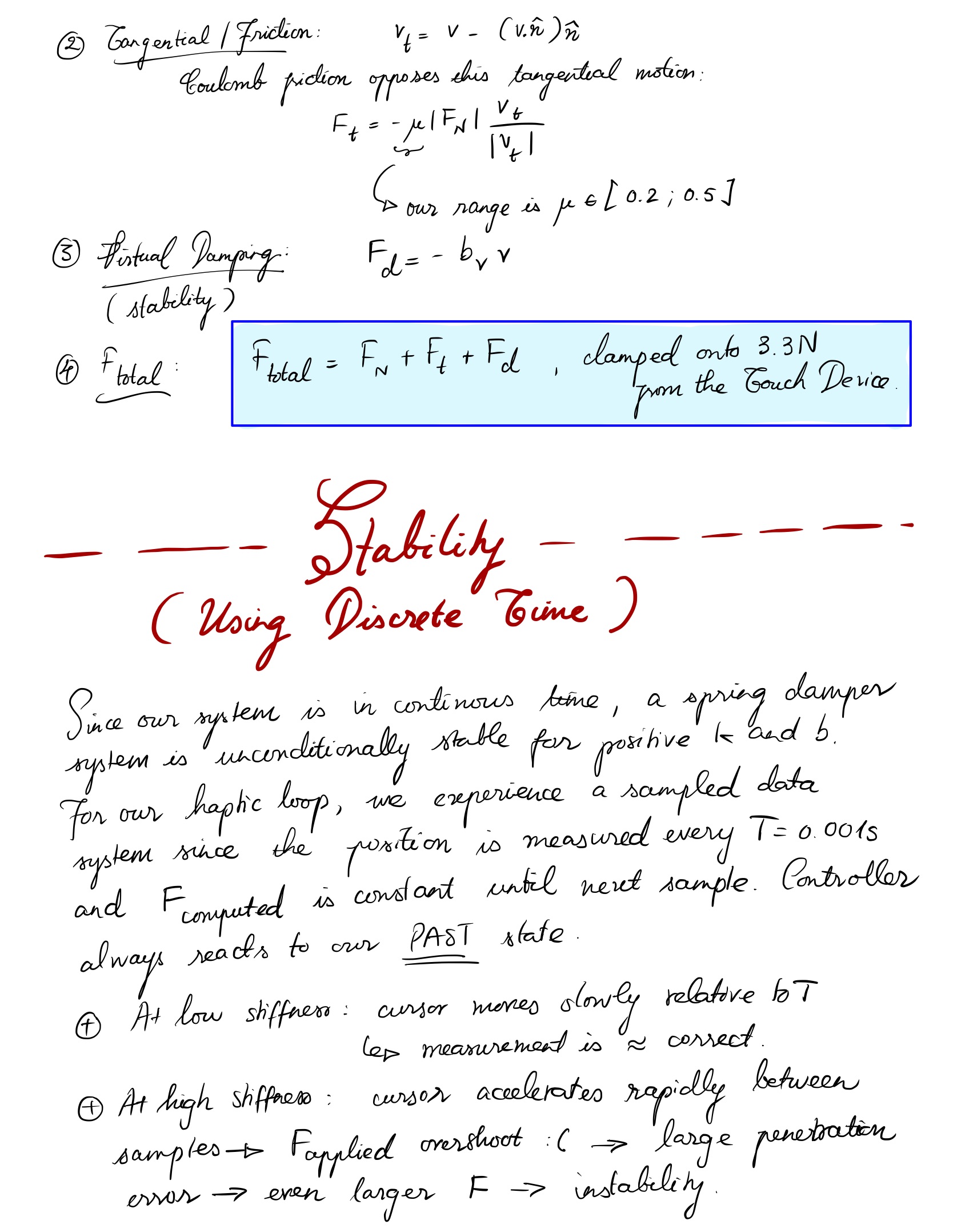
Contact force decomposition and discrete-time stability motivation
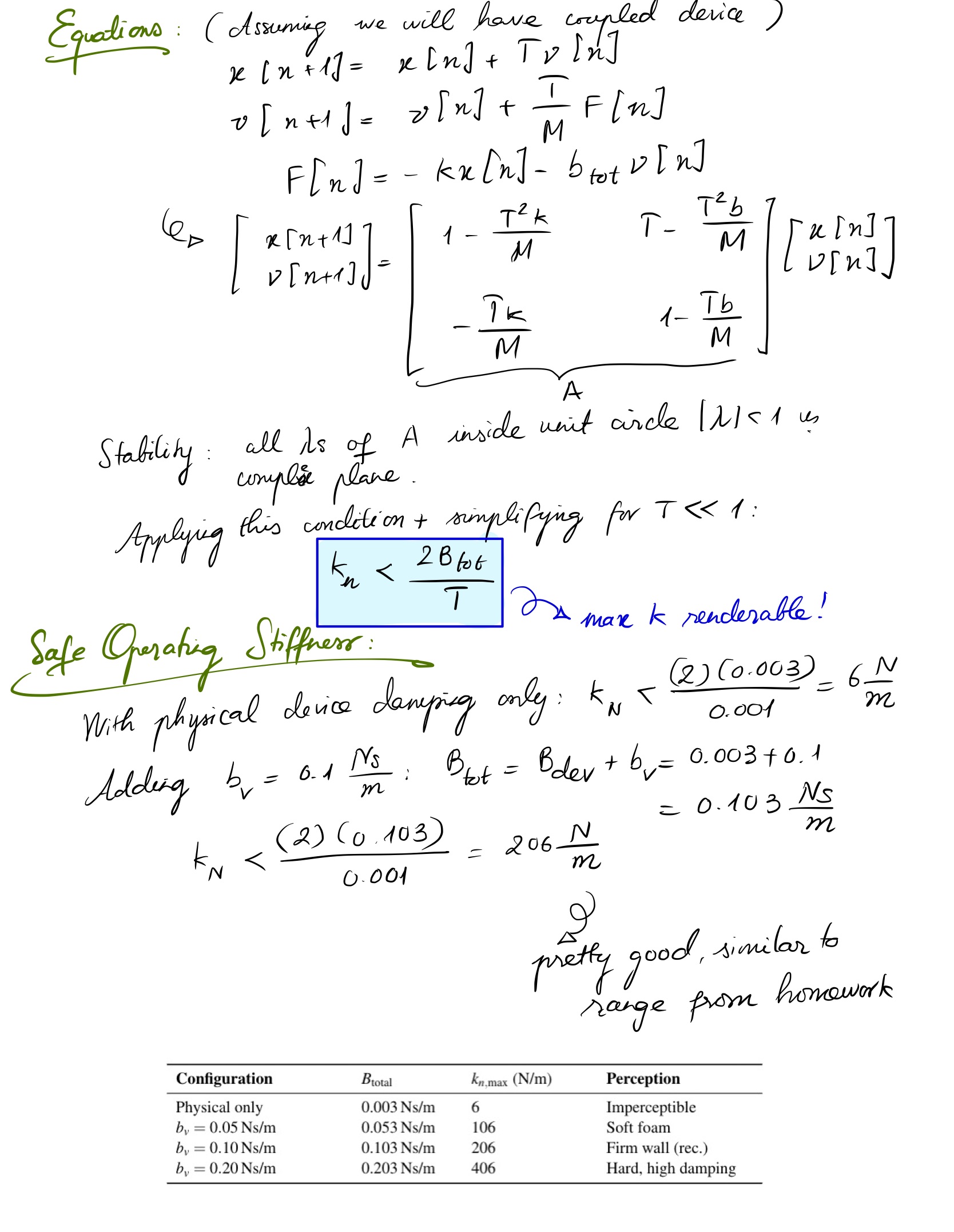
State-space equations, stability criterion, safe operating stiffness
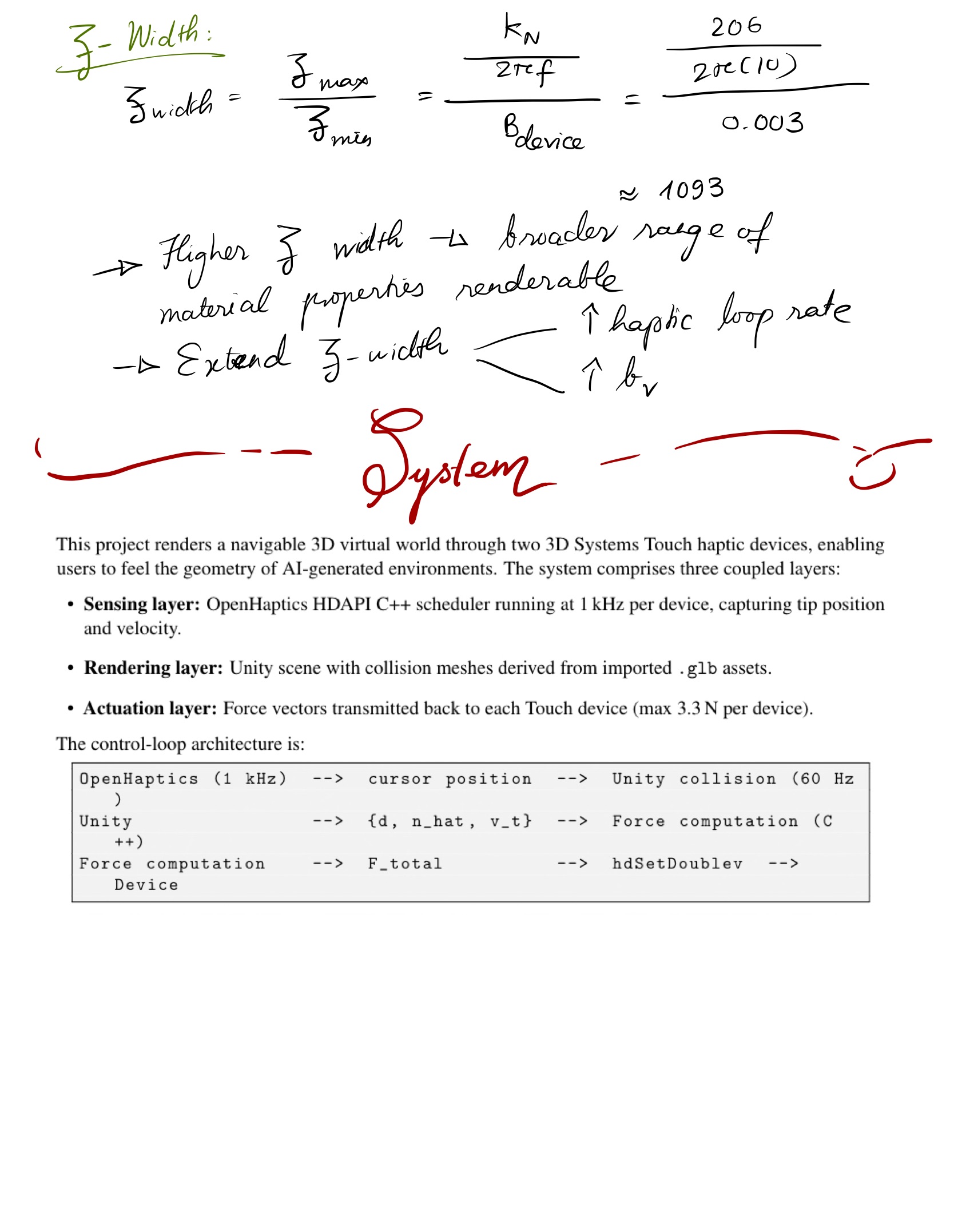
Z-width derivation and full system overview
Current Work in Progress
1. Combined .glb + Gaussian Splat Scene Integration We are currently working on integrating .glb geometry together with .ply/Gaussian Splat visualizations within the same Unity project. At the same time, we are experimenting with adding haptic force feedback (using C#) so that the user can physically feel interaction with the .glb environment through the 3D Touch device.
2. Testing with Low-Quality Marble .glb Assets The next step is testing the same interaction pipeline using lower-quality, instantly AI-generated .glb files. The goal is to evaluate how quickly generated assets behave inside the Unity + haptics workflow and determine whether simplified models are sufficient for rapid prototyping.
3. Collision Mesh and Visual Rendering Optimization We are also testing low-quality collision meshes for haptic force rendering while simultaneously using the .ply Gaussian Splat representation for improved visual quality during Play Mode. This approach aims to separate physics interaction from rendering complexity: • lightweight collision meshes for stable and responsive force feedback • high-quality Gaussian Splats for realistic visual appearance.