

2026-Group 9
Caption:
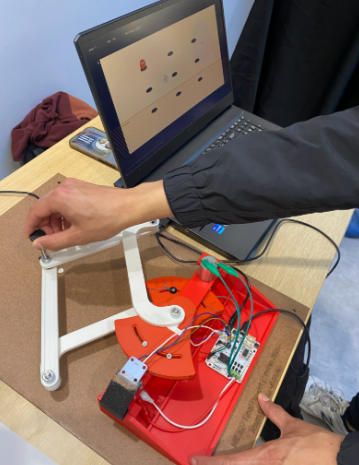
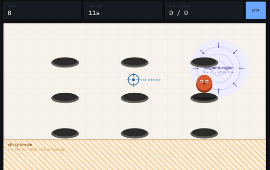
Whack-a-Mole in action!
Whack-A-Mole!
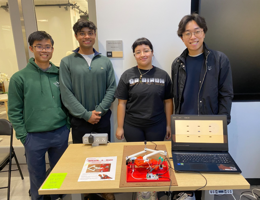
Project team member(s): Ethan Le, Ayaan Chand, Magaly Aviles, Odommoly Tranin
Our project was designed to be a haptic interface using a custom pantograph to simulate the experience of playing “Whack-a-Mole” in a fun and intuitive way using force feedback. The motivation for this project was to create an interactive haptic system that allowed us to explore the topics learned in class, such as force rendering, kinematic analysis, and testing different perceptual effects of virtual impedance. This allows the user of the game to understand how virtual objects can be connected to real physical forces. Our goals included designing and assembling a robust pantograph with position sensing and force feedback, integrating a proper virtual environment using Processing, and developing a model for tracking real-time motion during the game. Our resulting haptic device exceeds our goals and features two DC motors with encoders continuously measuring joint angles, integration of forward kinematics to map the readings to end-effector coordinates in real-time and additional controls described below in more detail. At the ME 327 Open House, we received a lot of positive feedback and comments on how the moles and various terrains could be easily distinguished during the game.
On this page... (hide)
Introduction
Our project is a haptic interface that was designed to imitate the experience of playing a Whack-a-Mole game in a virtual environment. The custom pantograph allows users to move the “hammer”, which is translated into the cursor movement in the game. Therefore, when users “hit” a mole, they feel a force response through the device, making the interaction easy to understand. In addition, we added various terrains to increase the difficulty of the game such as a magnetic region that would pull you away from the targets and a sticky region where the users moved slower due to damping.
Our haptic device is an appropriate approach because when a mole appears on the screen, the user moves the handle to catch it, and the system detects the contact and applies a feedback force. The device allows users to see and feel virtual objects due to the intentional integration of a mechanical linkage, magnetic encoder sensing, motor actuation, Arduino software control, and Processing graphics. Through this integration, we engaged with core concepts from the course. We implemented a forward kinematic model that allowed us to track the end effector in Cartesian space, and we followed with rendering forces with various stiffnesses and damping to ensure a smooth game.
The Whack-a-Mole game implementation as a haptic device made this an enjoyable experience for users and more accessible to people who may not have experience with haptics or controls. Overall, this project gave us the opportunity to design and build a haptic device that utilized various core class concepts.
Background
Through a literature review, we found foundational prior work in the field of haptic devices and applications that supported and influenced our project. Campions et al.’s, The Pantograph Mk-II: A Haptic Instrument, where they showcase their two-degree-of-freedom planar haptic device based on a five-bar linkage. Their device uses motorized joints and encoders to track endpoint motion and apply specific forces to the user through a small interface plate. For our project, we are using a pantograph mechanism to translate the physical handle movement into the endpoint position using kinematics. In addition, the paper highlights how the Jacobian transpose can be used to convert the endpoint forces into motor torques. This paper built the technical foundation for our haptic device as we are reading encoder values, calculating the handle position, and applying force feedback during mole impacts.
In addition, Tokuyama et al. 's work on their own Whack-a-Mole game with haptic feedback for rehabilitation showcases how crucial it is to ensure that both visual and gameplay are synchronized so the user interaction feels natural. In their system, the user interacts with a virtual Whack-a-Mole game and receives feedback when there is contact between the hammer and mole. Looking at the previous Whack-a-Mole work was important for our project because, in order for our project to succeed, the user should be able to easily move the pantograph handle to the mole and feel a force response at the moment of contact, and Tokuyama presents this clearly.
Finally, a third reference we found extremely useful is Toland et al.’s study on matched freespace and wall damping. Through a physical experiment, the paper states that damping affects how users perceive virtual objects and that the “feel” of a space before contact can influence how the user interprets a different environment. We implemented a sticky region in our project where users move more slowly due to damping. Our game uses force effects to change how the virtual environment feels when the user moves through it. This paper supported our specific design choices to include various terrains to increase the difficulty of the game.
Although there is incredible research focusing on the broad applications of haptics, by focusing on our project applications specifically allowed us to find support for both the mechanical and perception design. Prior work supports our design and goals of creating a haptic game where users can feel and see virtual interaction through a physical custom pantograph model.
Methods
Hardware Design and Implementation
The design of the pantograph is inspired by the previous years’ work and utilizes components from the Hapkit as the basis of the system. However, instead of the onboard magnetic encoder on the Hapkit board, we implemented two external magnetic encoder sensors (AS5600) that are powered using analog input pins. This allowed us to power all of the electronics using only one board, instead of communicating between two, as we did in Homework 6 (electronic schematic in checkpoint appendix). We used the magnetic encoders to measure the angles of the arms that were then processed to calculate the handle position through forward kinematics.
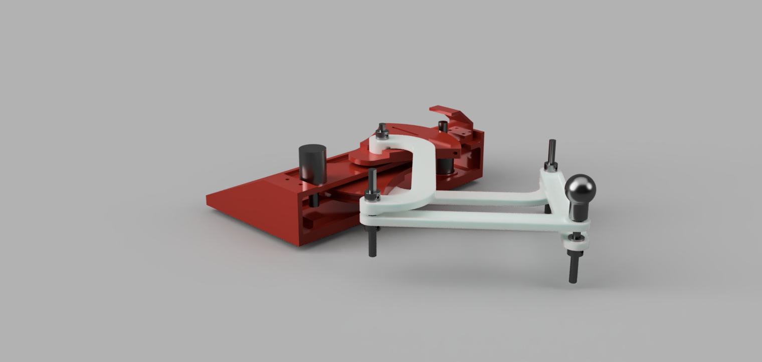
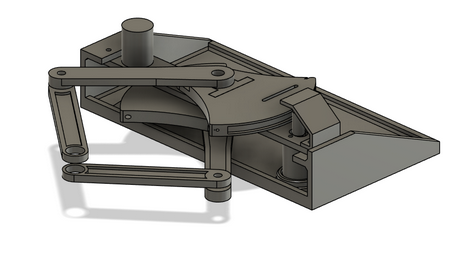
Our physical device was designed using Fusion and 3D printed at the PRL, where most parts were under the 3 dollar PLA limit, with the only exception being the base, which we printed for free at the Terman Library. The haptic device was designed carefully to ensure the user can move the handle freely while still being able to feel the force feedback.
Processing Graphics
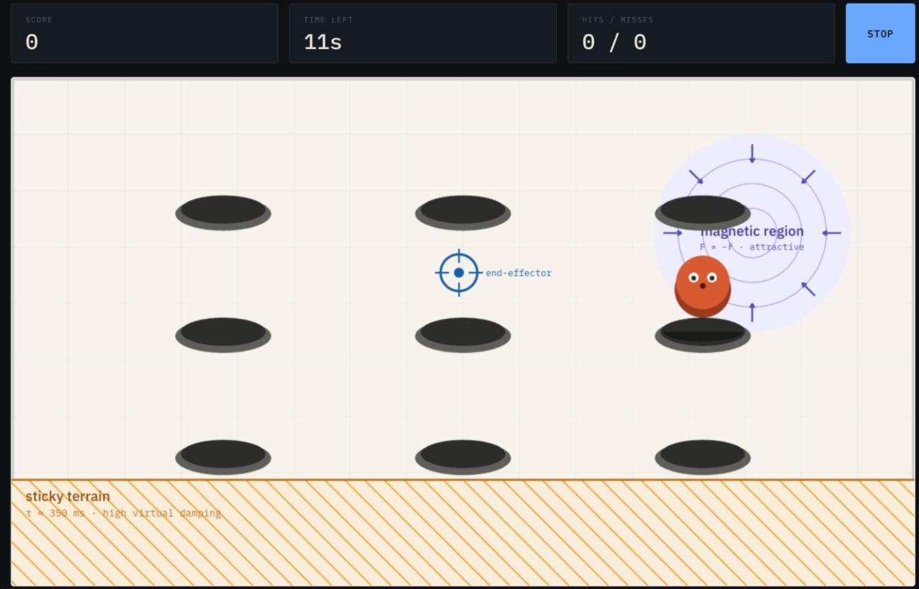
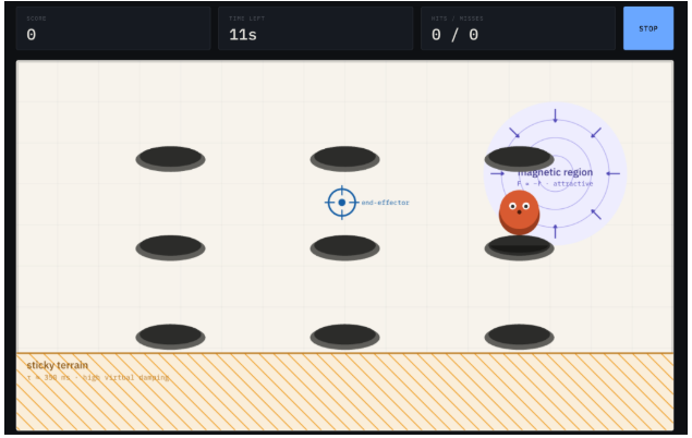
We built an interactive screen-side prototype of our game as a single standalone HTML file. The prototype renders the arena with a configurable hole grid (3×2, 3×3, or 4×3), a cursor representing the pantograph end-effector, and moles that pop from random unoccupied holes.
Inside the sticky terrain zone, lag is produced to mimic high damping. Inside the magnetic region, a constant inward force is added to the velocity command, equivalent to a one-sided spring rendered by the motors.
We chose the 3×3 hole layout as our default because it provides adequate target density without crowding the hammer footprint, and it keeps the workspace edges, where the Jacobian condition number is worst, clear of game elements. The magnetic region is positioned to overlap one hole in the top-right so that it functions as an aim-assist target rather than a hazard in dead space. Below is an image showcasing how the game looked while users played during the showcase.
System Analysis and Control
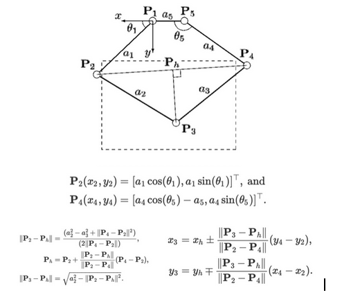
Since our system uses a pantograph driven by two motors, we needed a way to determine the motor torques required to produce a desired x-direction and y-direction force at the end-effector. To do this, we referenced The Pantograph Mk-II: A Haptic Instrument by G. Campion, Qi Wang, and V. Hayward, which provides the kinematic relationships used to map end-effector forces to motor torques.
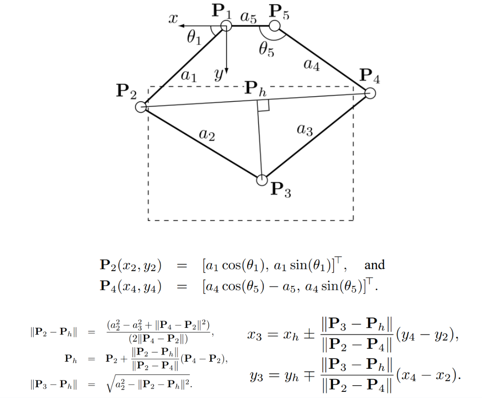
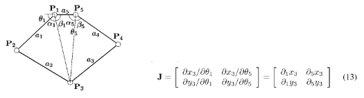
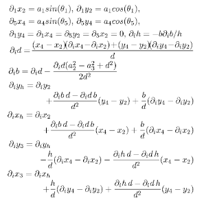
Using the following diagram, forces were rendered by applying the transpose of the Jacobian matrix as shown in the figure below. This maps desired forces into corresponding joint torques.
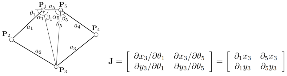
Finally, the partial derivatives used to build the Jacobian were calculated from the expressions shown below. These equations describe how the pantograph’s geometry changes as the joint angles vary, making them necessary for the computation of the motor torques in real time.
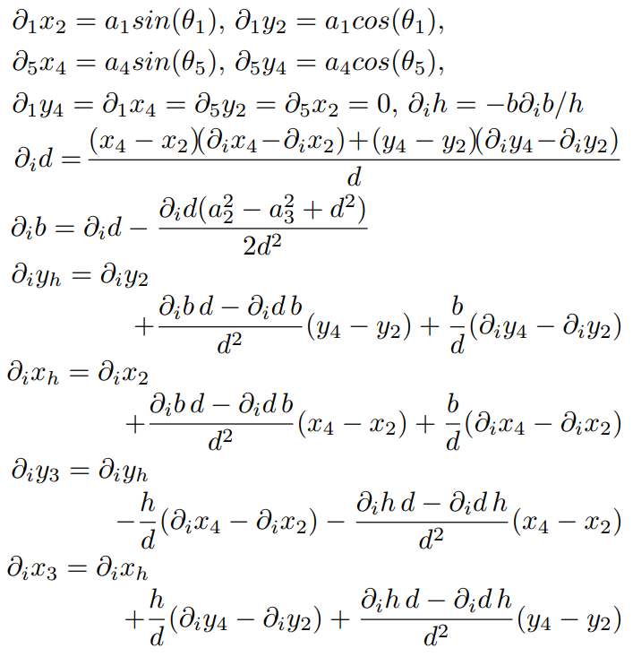
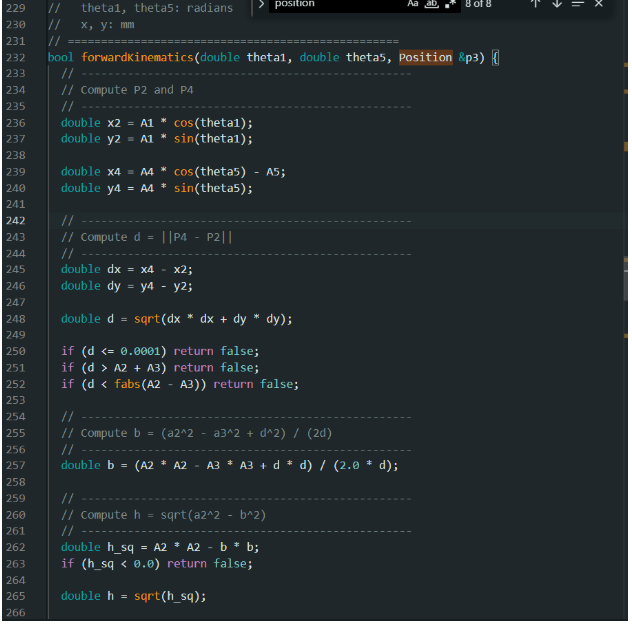
With all this in mind, encoders, after calibration, were used to measure the angles of theta1 and theta5. This, along with the knowledge of the values of links a1 through a5, were enough to determine the end effector position.
Once the end-effector position was known, we could render an appropriate force for each game element. The three interactions in our environment required three different impedance behaviors: a stiff one-sided contact when the hammer strikes an active mole, a viscous drag when the hammer enters the sticky terrain band, and a continuous attractive force when the hammer enters the magnetic region. All three forces were computed at the end-effector as a vector (Fx, Fy) and then passed through the Jacobian transpose described above to produce the corresponding motor torques. For mole contact, the mole was modeled as a circular virtual wall of radius rₘ centered on the active hole. When the hammer position penetrated this boundary, we rendered a one-sided spring plus damper force along the contact normal: F = k_c · (rₘ − d) · n̂ − b_c · v
where d is the distance from the hammer to the mole center, n̂ is the unit vector from the mole center to the hammer, and v is the hammer velocity. The stiffness term k_c · (rₘ − d) produces the restoring "wall" force, while the damping term b_c · v suppresses vibration near the contact boundary. For the sticky terrain band, we rendered viscous damping inside the zone: F = −b_s · v
We tuned b_s so that the hammer noticeably lagged behind the user's hand inside the band without fully stopping motion. The choice to keep free-space and sticky damping within the same order of magnitude is informed by Toland et al., who showed that participants classify wall stiffness most accurately when free-space damping is similar to wall damping; we applied the same logic at the boundary between free space and our sticky band.
For the magnetic region, we rendered a constant inward force whenever the hammer was inside the disk: F = F_m · (c − p) / ‖c − p‖
where c is the magnet center, p is the hammer position, and F_m is the force magnitude. The force is independent of distance inside the disk, so the pull feels equally strong everywhere in the region and only releases when the hammer crosses the boundary.
The three forces were summed at the end-effector and the resulting (Fx, Fy) was passed through the Jacobian transpose to compute the joint torques (τ1, τ5), which were then converted to motor torques through the Hapkit sector drive ratio (rp/rs) before being written to the PWM driver.
Results
At the project open house, we invited users to interact with our haptic Whack-a-Mole system and provide feedback on its responsiveness, realism, and overall engagement. The responses were overwhelmingly positive and suggested that many of our core design goals, particularly those related to haptic perception and immersive feedback, were realized.
Overall, users appeared to enjoy playing the game. Many participants were engaged by the familiar Whack-a-Mole format and responded positively to the interactive nature of the system. The combination of visual feedback, physical motion through the pantograph, and haptic force feedback made the experience more dynamic than a standard computer game. Several users specifically commented on the tactile realism of the mole interactions. Comments such as “I can definitely feel moles” and “It’s satisfying to hit them” indicated that the system was effective in communicating the sensation of striking a mole.
We also received valuable feedback on some of the additional haptic effects, such as the magnet and sticky zone features. During the first part of the open house, we allowed users to begin playing immediately with minimal explanation. In these early trials, some participants reported that they did not initially notice the difference or effect from the sticky zone and magnet. However, after prompting and us adjusting our explanation and briefly introducing the different environmental features before gameplay, users were then able to recognize and positively comment on these effects. This suggests that the magnet and sticky zone forces were present, but may not have been strong or distinct enough to be immediately noticeable without prompting.
Overall, the open house results validated many of our design goals, while also identifying areas where the haptic rendering could have been made more intuitive and noticeable.
Video of haptic device in use during Haptics Showcase: Attach:IMG_5206.MOV
Future Work
There are several ways that the system could be improved in future iterations, particularly with respect to gameplay, haptic rendering, and hardware performance.
Regarding gameplay, one possible improvement would be to add more complex terrain to the virtual environment. Instead of only rendering static, discrete haptic regions, the game could include peaks, valleys, slopes, or obstacles that generate corresponding forces as the user moves through the space. In addition, another gameplay improvement would be to make the course more dynamic. In our current implementation, haptic features such as the magnet and sticky regions were fixed. Future versions could allow these regions to move around the screen, appear and disappear, or change strength over time, making the game more challenging and allowing the haptic feedback to play a larger role as well.
On the hardware side, the system could be improved by using higher-quality encoders. The relatively inexpensive encoders used in our project made accurate position tracking a bit difficult, due to inaccurate readings, requiring a significant amount of calibration and many software-based corrections to make the measured position match the actual position of the pantograph.
Additionally, the motors could be improved in future versions. More powerful motors would allow the system to render stronger forces and a wider range of haptic sensations while still maintaining stability. This would be especially useful for effects such as the sticky zone, magnet, and recently suggested terrain effects, since stronger force output would make these interactions easier for users to distinguish.
Finally, the last mechanical improvement would be to address cantilevering in the pantograph structure. During use, the pantograph could bend or deflect slightly out of plane, which affected the smoothness and consistency of motion. Using a stiffer frame, or additional support structures in the future to reduce this issue would make the device feel more robust and improve the quality of the rendered haptic forces.
Overall, the system functioned well as a prototype and demonstrated the potential for a more engaging haptic arcade experience. With the potential aforementioned improvements, future versions could become more immersive, reliable, and suitable for real-world arcade-style applications.
Files
CAD File: Attach:Team9_CAD.zip
Arduino Code: Attach:whacamole_code.zip
Processing Code: Attach:whacamole_graphics.zip
Bill of Materials:
     - Bushings : $11.6

     - Shafts: $14.7

     - Shaft Collars: $9.9

     - Encoders: $10.90

     - Bearing: $3.75
References
Campion, G., et al. “The Pantograph Mk-II: A Haptic Instrument.” 2005 IEEE/RSJ International Conference on Intelligent Robots and Systems, Aug. 2005, pp. 723–728, https://doi.org/ 10.1109/IROS.2005.1545066.
Tokuyama, Yoshimasa, et al. “Development of a whack-a-mole game with haptic feedback for rehabilitation.” 2016 Nicograph International (NicoInt), July 2016, pp. 29–35, https://doi.org/10.1109/nicoint.2016.6.
Toland, Madeleine, et al. “Effects of matched freespace and wall damping on stiffness perception.” 2026 IEEE Haptics Symposium (HAPTICS), 29 Mar. 2026, pp. 1–7, https://doi.org/10.1109/haptics66823.2026.11495487.
Appendix: Project Checkpoints
Checkpoint 1
To highlight the progress we have made to finish our tasks we will outline the progress for each section separately below:
CAD Progress:
The CAD of the pantograph system is primarily done, with the exception of hardware, which we plan on purchasing from AMPS. The pantograph design is inspired by the previous years’ work and utilizes components from the HapKit, with the addition of two magnetic encoder sensors (AS5600) for each motor.
Rendering Virtual Environment Progress:
We built an interactive screen-side prototype of our game as a single standalone HTML file. The prototype renders the arena with a configurable hole grid (3×2, 3×3, or 4×3), a cursor representing the pantograph end-effector, and moles that pop from random unoccupied holes.
Inside the sticky terrain zone, lag is produced to mimic high damping. Inside the magnetic region, a constant inward force is added to the velocity command, equivalent to a one-sided spring rendered by the motors.
We chose the 3×3 hole layout as our default because it provides adequate target density without crowding the hammer footprint, and it keeps the workspace edges, where the Jacobian condition number is worst, clear of game elements. The magnetic region is positioned to overlap one hole in the top-right so that it functions as an aim-assist target rather than a hazard in dead space, though we are still deciding whether to keep this overlap in the final design. The sticky band along the lower edge of the arena gives us a controlled location for testing the stiffness-classification effects.
Acquiring Materials and Hardware Progress:
As stated previously in our CAD progress section, our hardware will be purchased from AMPS. In addition, we will be using the motors provided with our Hapkit, paired with magnetic encoder sensors we will purchase from Amazon. For any 3D printed parts, we will also be printing them at AMPS. The virtual game will be displayed on a laptop and no additional hardware will be required.
Motor Calculation Progress:
Originally, we had planned to perhaps purchase motors with integrated encoders to use for our device, like the following Pololu motors (https://www.pololu.com/product/4881 .) However, after further discussion we as a team decided against it due to the relatively high cost. Instead, we will be using the motors provided with our Hapkit, and have purchased magnetic encoder sensors to be paired with these motors in a similar setup to how the Hapkit is assembled. As a result, since no new motors are being purchased, there is no need for motor calculations.
Electronics Schematic:
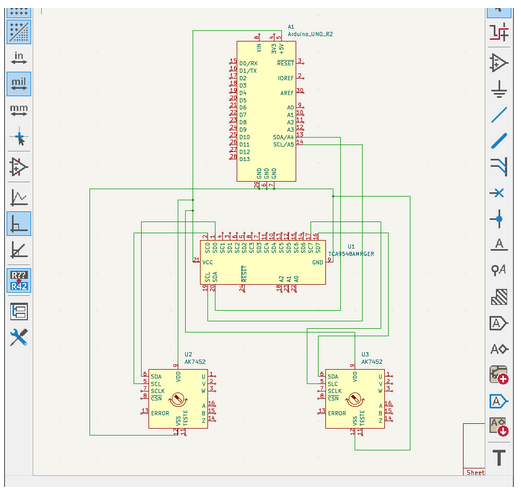
Since we plan to use two AS5600 magnetic encoder sensors, we ran into a communication issue because both sensors use I2C and share the same fixed I2C address. Although the Hapkit board only provides one I2C communication bus, two devices with the same address cannot be connected directly to that bus because the controller would not be able to distinguish between them. To solve this, we will use a TCA9548A I2C multiplexer, which allows each AS5600 sensor to be connected on a separate I2C channel. The Hapkit board can then select which channel to communicate with, allowing it to read both encoders independently. The finalized electronics schematic can be seen below:
Pantograph Force Feedback:
Since our system uses a pantograph driven by two motors, we needed a way to determine the motor torques required to produce a desired x direction and y direction force at the end-effector. To do this, we referenced The Pantograph Mk-II: A Haptic Instrument by G. Campion, Qi Wang, and V. Hayward, which provides the kinematic relationships used to map end-effector forces to motor torques.
Using the following diagram, forces were rendered by applying the transpose of the Jacobian matrix as shown in the figure below. This maps desired forces into corresponding joint torques.
Finally, the partial derivatives used to build the Jacobian were calculated from the expressions shown below. These equations describe how the pantograph’s geometry changes as the joint angles vary, making them necessary for the computation of the motor torques in real time.
Next steps will focus on global position tracking of the pantograph end-effector, as in order to render forces accurately, we need to continuously track the horizontal and vertical position of the handle. This would include us mapping the traced path of the pantograph to better understand its full range of motion, and define the usable workspace of the device.
Overall, we are very pleased with the progress we have made and we feel very confident to meet our future checkpoint. We are excited to begin printing and assembling our final device.
Checkpoint 2
CAD Progress: CAD model finalized:
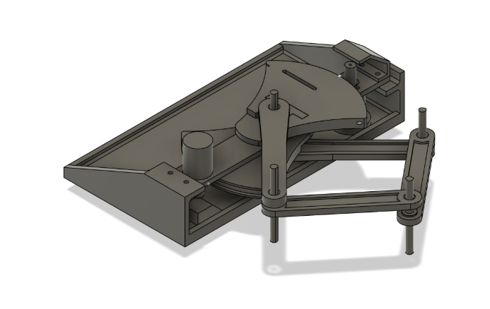
The CAD model of the pantograph system is now finalized and shown above. Since the previous checkpoint, we have completed the full mechanical design and confirmed the final geometry of the pantograph mechanism.
Physical model printed:
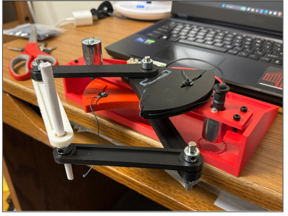
The physical model has been printed, and we have assembled the pantograph mechanism. In addition, we have purchased the required electrical hardware components, including the two magnetic encoder sensors.
However, our electrical components have not arrived yet and are expected to arrive tomorrow morning. As shown in our previous checkpoint, we already have the electrical schematic prepared, which will allow us to integrate the electronic components easily once they arrive.
Rendering Virtual Environment Progress:
For the virtual environment, our program follows the Assignment 3 starter code and runs both the game logic and rendering. The current game renders the arena, displays the moles, tracks the cursor position, and supports hit detection when the user interacts with the moles.
We have finalized the main Processing code structure and will continue fine-tuning the game once the electrical components are integrated with the physical pantograph device. At this stage, the main virtual environment loop is working, and our next goal is to connect the physical haptic device motion directly to the game cursor.
Free-Space Motion, Impedance Controller, and Calculation Progress:
In our previous checkpoint, we completed the force feedback hand calculations for our pantograph device. Following those calculations, we focused on global position tracking of the pantograph end-effector. This allows us to continuously track both the horizontal and vertical position of the handle.
As we developed our software, we also mapped the traced path of the pantograph to better understand the motion and usable workspace of the haptic device.
Our code calculates the end-effector position using forward kinematics and converts desired endpoint forces into motor torques using the Jacobian transpose method. In addition, the Arduino sketch handles the motor torque commands and force rendering.
With the impedance controller, the device will calculate force based on the handle’s position and velocity. This will help ensure that the device feels transparent during free-space motion and only applies noticeable forces when the user interacts with objects in the game.
Once our motor electronics arrive, we will tune the impedance controller so that free-space motion feels smooth and transparent, while interaction with the game produces haptic feedback.
Overall Progress:
Overall, we have made strong progress this week. The CAD model is finalized, the pantograph has been printed and assembled, the virtual environment is working, and the main kinematic and force-rendering calculations have been implemented in software.
Our next steps are to integrate the arriving electrical components, connect the physical pantograph to the virtual environment, and tune the impedance controller for transparent free-space motion and effective haptic feedback.