

Group 12
Demonstration of our project setup.
Two-player Interactive Air Hockey with Haptic Feedback
Project team members: Ken Wang, Yimeng Qin, Shanlin Chen, Junnan Yu
In this project, we designed and built an interactive gaming device that allows two players to remotely play air hockey against each other. Our goal was to build a functional prototype that gives users a nice feeling of playing air hockey. After completing the prototype and implementing the haptic rendering, we explored the factors that affect the realism of human perception and reflected on potential improvements that could be made in order to provide a better gaming experience.
On this page... (hide)
Introduction
Air hockey is a popular game that is adored by many people, but it could not be played by two friends in different places, so the game is missing some applicability in a remote setting. We hope that our project could bring an innovative solution to this issue by creating a haptic illusion of mallet-puck collision, which is physically produced as vibrational force feedback felt by users. Specifically, this topic involves hardware design of the mallet, circuit configuration, Arduino-host computer communication, and haptics rendering. A virtual environment was established using a game engine which helps define an open space where users can freely move the handle and see the ball trajectory. The collisions are defined and mallet/puck positions are correspondingly updated. Meanwhile, we want the device to have a decent performance in terms of its system noticeability and stability in haptic rendering. We believed that this project would have an engaging demo part, in which two volunteers could enjoy playing and exploring this attractive game setting on the demo day.
Background
As described in the blog post "Sony�s augmented reality air hockey is better than the real deal" [1], the A(i)R Hockey project presented by Sony at the 2018 SXSW conference has a very similar concept as our project. The Sony version performs tracking through a high speed camera (1000 FPS) that tracks the location of the 4 handles at the same time. Instead of providing vectored force feedback, they also used vibration motors to render the haptic effect of the contact. According to the report, this actually results in a rather high level of authenticity of feeling like actually hitting the ball. They also added sound effects to further immerse the players. There are a lot of illusion tricks we can extract from their project and increase the level of immersion of our project.
The authors of the paper "Realistic Haptic Rendering of Collision Effects Using Multimodal Vibrotactile and Impact Feedback " [2] designed a multimodal haptic rendering method for virtual collisions by using an exponentially-decaying sinusoidal model for vibrotactile stimuli and a pulse model for impact stimuli to better render collisions between highly stiff objects. This 1-DoF haptic rendering device combines an impact actuator consisting of a permanent magnet and three solenoids, and a voice-coil actuator as the vibrotactile actuator. Each actuator in this device can function separately. By testing each (impact, vibrotactile, combined) method�s effectiveness in rendering virtual ball drop of steel-ball-steel-plate, wooden-ball-wooden-plate, and rubber-ball-concrete-plate, they conclude that for highly stiff objects, the combined method works best (highest realism & lowest unnaturalness & highest liking); for modest modestly hard objects, methods that include an impulse function better than vibration rendering; while for soft objects, different rendering methods do not cause a significant difference.
In "Simulating and displaying of puck motion in virtual air hockey based on projective interface" [3], the authors implement air hockey gaming based on the Image-projective Desktop Arm Trainer (IDAT). Specifically, they focus on solving three main difficulties rising along with the IDAT method. First of all, since the scanning rate of the sensor is too low to update the mallet position, this paper uses multiple timers to synchronize the position data. Second, the hand misrecognition problem is solved using the hand owner recognition algorithm. Additionally, they present detailed work on the calculation of their physical gaming engine. They presented algorithms to solve the problems such as the puck position updating frequency mismatching with the mallet updating frequency, how to prevent the puck accidentally passing through the mallet, and the velocity calculation being affected by different events.
The studies completed in �QoE assessment in networked air hockey game with haptic media� [4] address the Quality of Experience (QoE) of output quality and interactivity in a networked air hockey game played by two players with a haptic media. Each user uses a PHANToM Omni as the haptic interface and virtually moves the mallet in the constructed environment by actually operating the stylus that sends media units (MUs) including the information units for causality control and dead-reckoning. The authors use adaptive ∆-causality control scheme with adaptive dead-reckoning and clarify the influence of network delay on QoE. As a result, a significant deterioration in QoE is observed as the network delay becomes larger. In our project, various system information (position, velocity, acceleration, time-stamp, etc) are updated at each time step.Therefore, having a low time delay in the communication between an input MU is generated and an output MU is given to the terminals will benefit the mallet interactivity, force feedback when colluding with the puck, and other factors which make up the comprehensive quality of haptic rendering.
Methods
Hardware design and implementation
We started the project from designing the mallets that would hold all the components and have a rather ergonomic shape. We need 4 vibration motors for each mallet to provide haptic feedback and two more time-of-flight (TOF) range sensors to keep track of the locations of the mallet in the arena. All peripheral signals are connected to the Arduino as the central hub. To drive the four motors, we also need to provide an external power source that is regulated by a MOSFET since the current output from Arduino pins is rather limited. Specifically, each motor should be connected according to the following diagram:
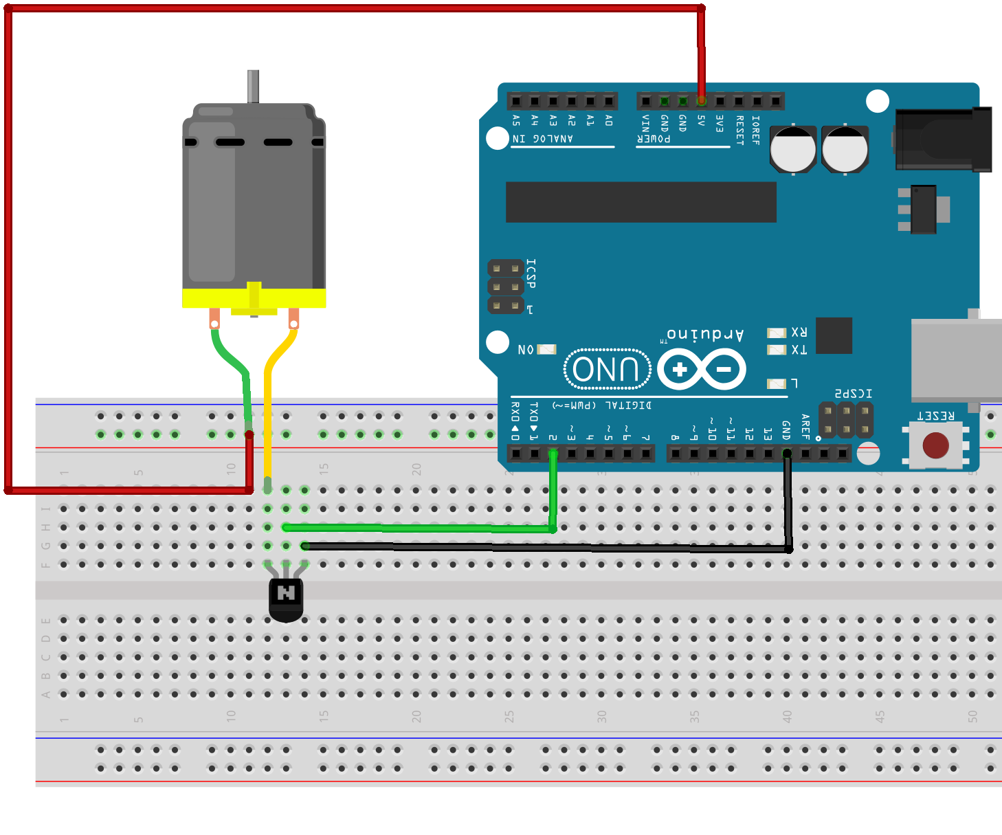
Figure 1. MOSFET connection to a DC motor.
Combining all of the above, the wiring of one full mallet is shown below:
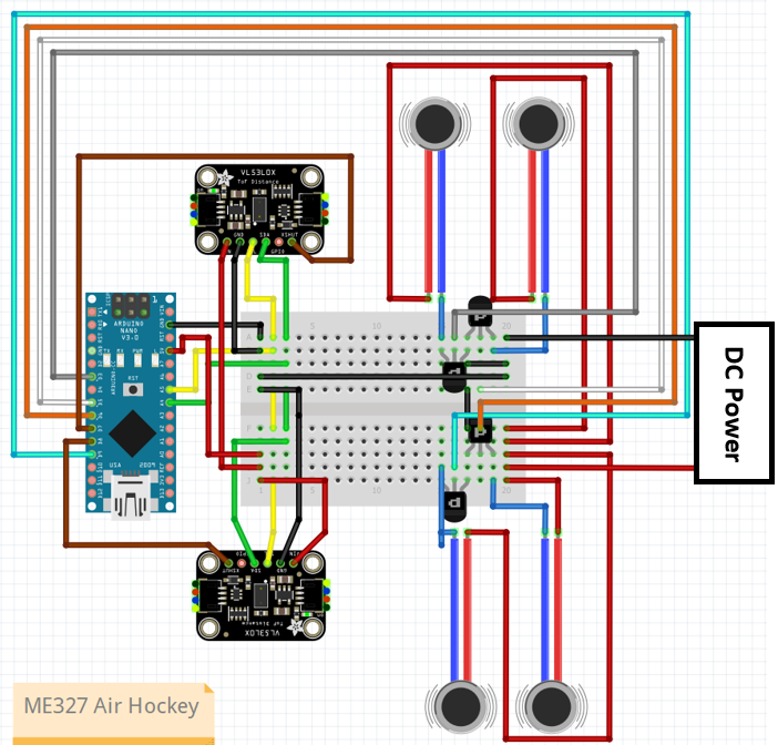
Figure 2. Circuit design.
The mallet is designed so that the vibration motors are mounted inside the wall with sensors pointing outwards. The base is printed with FDM 3d printer and the top handle is printed in resin for a better look. The rendering of the mallet is shown below:
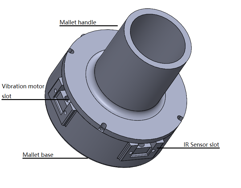
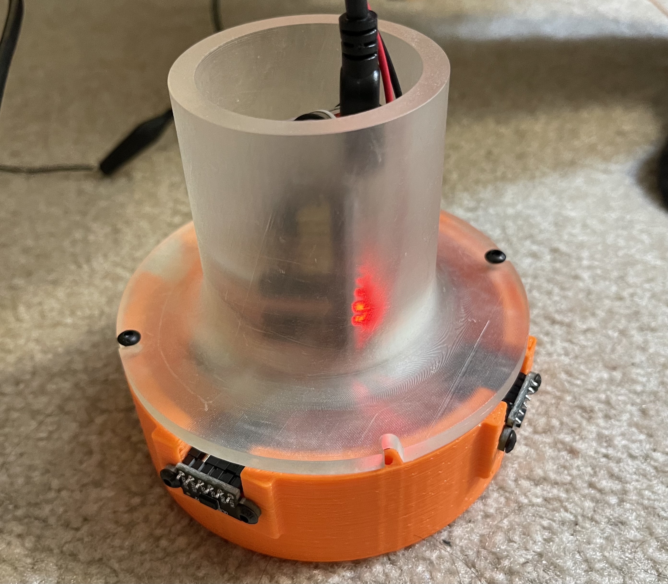
Figure 3. left: CAD design of mallet. right: Assembled mallet.
In the Arduino code, we are listening on the serial communication whether the computer has sent a vibration command. Each command will cause the mallet to vibrate for 35ms. Depending on the strength of the collision, the computer might send multiple signals to induce a stronger haptic feedback. The code also handles the sensor data collection and it will send the range detected in millimeters at 30Hz.
In specific, the positions of mallets moving in two arenas are collected by IR sensors and transferred to a host computer via Arduino. The simulation is done on a host computer that computes the ball locations and displays to both players, while the force commands are sent to the mallets through serial communication whenever needed.
Software
Now we can build the simulator environment with Arduino ready to serve as the exchange hub. We went with the Unity game engine for its better graphic and more robust collision detection. We created a room space inside the Unity populated with objects and an air hockey desk in the middle of the room. To handle the serial communication, we wrote a game script in C# that reads and converts the range readings to game coordinates, and it is able to be sent to Arduino when necessary.
The collision between objects in the game is done in a rigid body manner. Specifically, the puck is allowed to move in the desk plane and rotate about the z-axis, while the mallet is not allowed to rotate (since the sensor setup does not allow rotation) but free to move in the desk plane. The collision detection and triggering are managed by another script we wrote that runs in a loop inside Unity. When collision happens, depending on the penetration distance, the script will send one or multiple commands to the serial manager so that the mallet can alert the user the hit intensity. We had some numerical issues in the implementation that the ball will ignore the mallet and cross to the other side of the mallet, but it all goes away when we decrease the time step.
Initially we also implemented the directional haptic feedback, meaning that depending on the bearing of the hit, the Arduino will choose to activate only the motors closest to the hit direction. However we quickly learn in testing that the handle is so rigid that the vibration is transmitted to the whole handle and user is unable to tell the direction, which is something we could improve.
We also achieved our reach goal to make two handles so that the game is a multiplayer game, which adds a lot of fun to the demo. To complete the game experience, we added a goal reset script that replace the ball to the arena center when it detects the puck colliding with the goal post. We also added a scoreboard which show the which of the users has scored more.
Demonstration / application
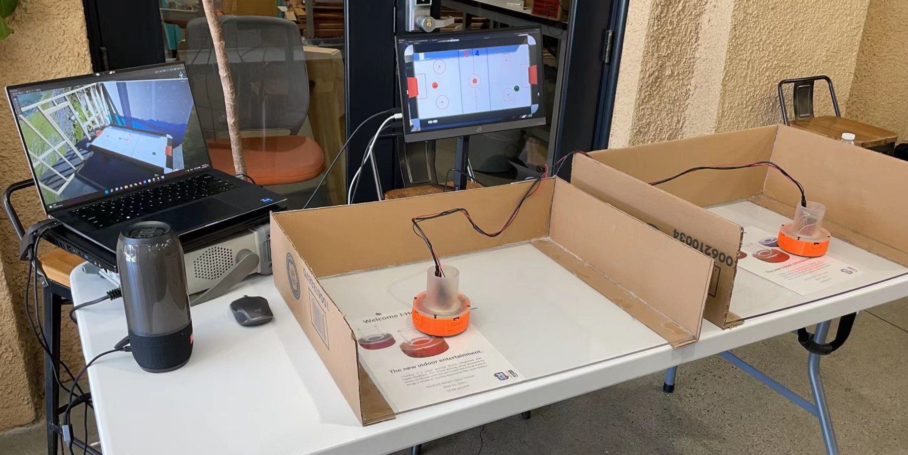
The demonstration setup:
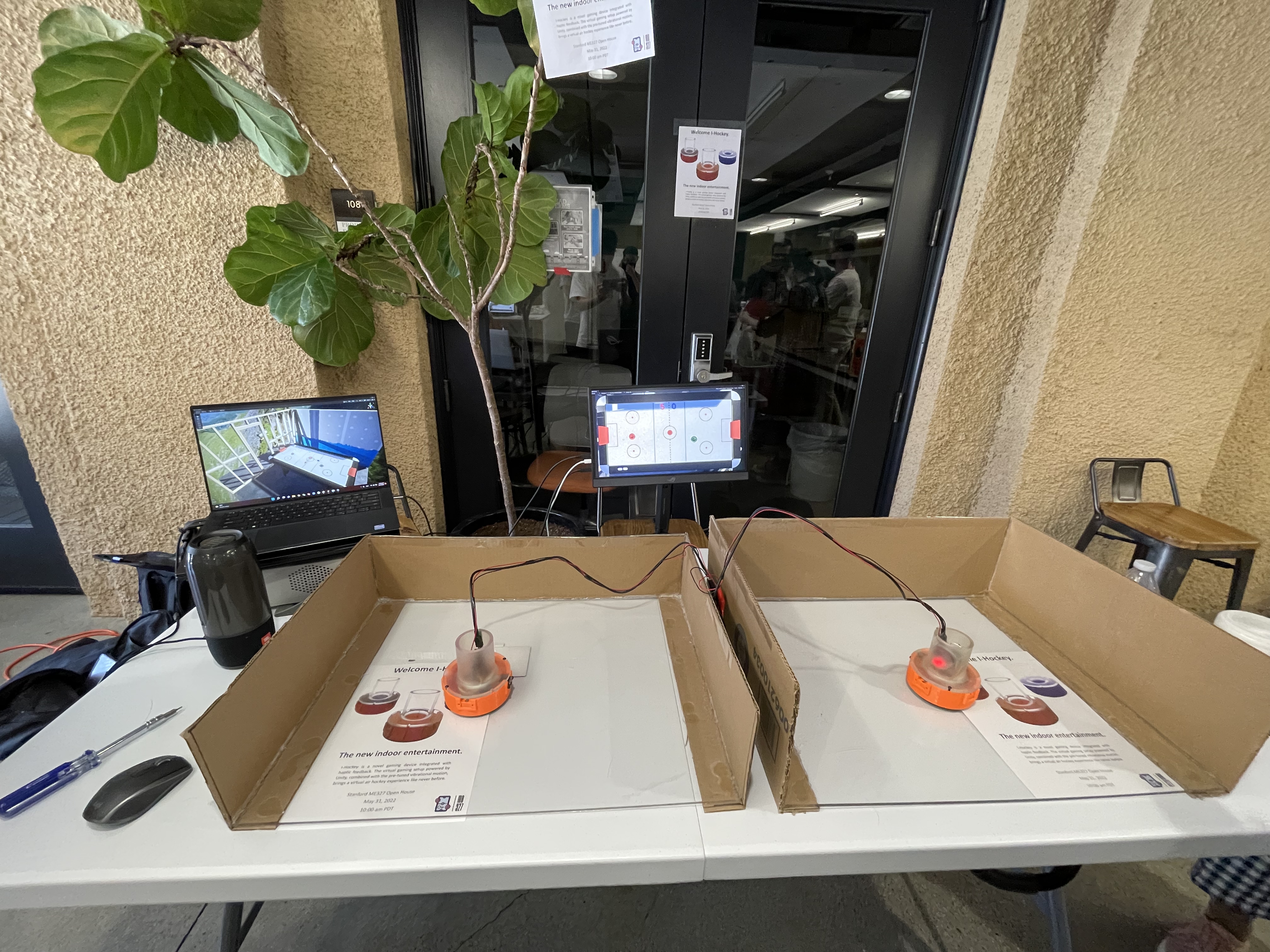
Figure 4. Setup on demo day.
Example gameplay can be found here: https://youtu.be/PSW3R4jmgYI.
Results
At the end, we achieved the initial goal of building a fully functional air hockey gaming device that operates based on haptic rendering. Two mallets were made using 3D printed physical parts with vibrational motors and IR sensors properly installed. Except the Arduino cord and powering wires to functional generator, all the other wires and the breadboard are put inside each of the two mallets, which are put on two arenas with acrylic glass surfaces. Code written in Unity, which creates the virtual environment and takes care of the bi-directional signal transfer (position detection from IR sensors and force commands sent to vibrational motors), was finalized. All these were thoroughly tested to be working successfully in the preparation stage for the demonstration day.
On the demo day, we got a lot of positive feedback from the people who tried our device. As reported by the users, they felt the game was highly realistic because of the lively changing mallet position on the screen based on physical movement of actual mallets and the sound effect that is played at moments of collision. When playing the game, the audience also mentioned that the force commands sent back to vibrational motors on mallets helped create the realism as well as noticeability felt at their hands. When it comes to stability, most people thought that the mallet movement is accurately reflected and quickly updated in the Unity interface with little overshoot. Overall, the device achieves a successful haptic rendering and smooth operation.
Our Project Team
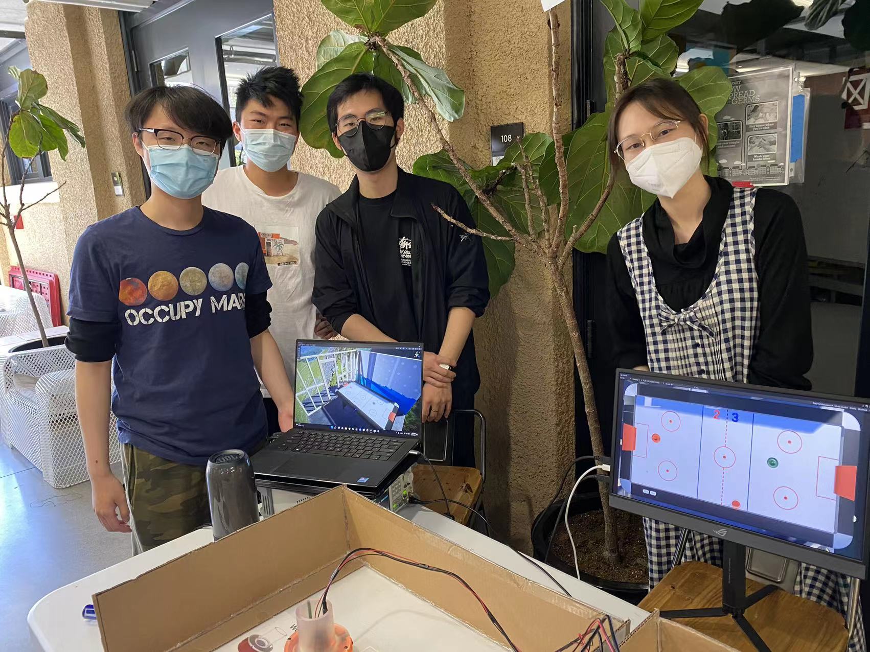
Figure 5. Project team members.
Starting from left: Ken Wang, Junnan Yu, Yimeng Qin, Shanlin Chen
Future Work
During this project, we tackled the technical difficulties to fully implement a haptic rendering device and built a smooth connection between software and hardware, but there are still a couple of aspects that could be potentially improved.
First of all, we believe that the mallet position could be measured differently in order to give user more freedom in their hand movements. Right now the mallet positions are measured by IR range sensors installed perpendicularly, so the players must have a constant orientation when holding the mallets so that the distances to arena sideboards could be accurately collected. The IR sensors must not be blocked either. If using a camera placed vertically up from the arena to capture top views, the positions can be directly defined in a 2-D sense with proper mapping between camera images and arena dimensions. Hence, the users could have more freedom in their free space because they could rotate the mallets if they want to. Alternatively, we could implement a similar working principle of a Bluetooth mouse by putting the sensing mechanism of the mouse into the mallet, so the mallet movement could be conveniently depicted with a receiver plugged into the host computer.
There are also some other technical aspects of this project that we could implement in the future. Currently, we have a wired serial communication between physical mallets and gaming software. The power supply of the mallets is also wired, so the playable range is limited by the length of the wires. In the future, we could have the mallet wirelessly communicate with the host computer via Bluetooth or have the mallet carry battery cells to power the vibration motors. Another thing we could improve is the circuit design. Currently, we build our mallet control circuit on a breadboard, which takes a lot of space inside the mallet, and the pins might get loose if the users move the mallet too aggressively. We could build a PCB for our final circuit design to increase the circuit reliability and make the hardware more compact. Finally, we implemented the idea of directional haptic feedback, but the users were unlikely to pick up the directional effect due to the rigidity of the mallet base. We can try to make the mallet with a material that has more damping than resin so that the user could feel stronger vibration in a particular direction.
Also, we could add an arcade mode to the game to give even more interactivity and fun. For example, at a random moment a "gift box" appears somewhere on the virtual air hockey table. The user who first hits it with his/her mallet could get an advantage like freezing the opponent's mallet for 2 seconds, making the opponent's mallet tiny for a short while, or making the opponent's goal much bigger for a short while.
Furthermore, we could create two separate views for the players, so each could watch an individual screen instead of sharing the same one. With a host computer showing a 3-D view, we could connect it with two monitors that display opposite views. This way they both would have a feeling of hitting the puck forward, which helps improve realism since people stand across from each other on the two short sides of a table when playing real air hockey. If integrated with VR, the users would get a fully immersive air hockey experience.
Files
CAD model for the mallet: https://drive.google.com/drive/folders/1U-oIWMlQqROwavTcPS68JHsmyWQFBF0_?usp=sharing
Gaming environment in Unity: https://drive.google.com/drive/folders/1JhSPRPXuDlpWSTSeO0NG7Lq-SZM0S0JY?usp=sharing
Arduino control code: https://drive.google.com/drive/folders/1-NJ2ZTQ3PIH0BliY03CUNrx-tMzpBQTr?usp=sharing
References
[1] Karissa Bell, Sony�s augmented reality air hockey is better than the real deal, Mashable, 2018. URL: https://mashable.com/article/sony-augmented-reality-air-hockey
[2] C. Park, J. Park, S. Oh and S. Choi, "Realistic Haptic Rendering of Collision Effects Using Multimodal Vibrotactile and Impact Feedback," 2019 IEEE World Haptics Conference (WHC), 2019, pp. 449-454, https://doi.org/10.1109/WHC.2019.8816116.
[3] C. Dai and T. Matsumaru, "Simulating and displaying of puck motion in virtual air hockey based on projective interface," 2015 IEEE International Conference on Robotics and Biomimetics (ROBIO), 2015, pp. 320-325, doi: 10.1109/ROBIO.2015.7418787. URL: https://ieeexplore.ieee.org/document/7418787
[4] Kusunose et al., �QoE assessment in networked air hockey game with haptic media,� 2010 9th Annual Workshop on Network and Systems Support for Games, 2010, https://doi.org/10.1109/NETGAMES.2010.5680284.
Appendix: Project Checkpoints
Checkpoint 1
In our project proposal, we proposed the following target for the checkpoint 1:
May 12th: Order parts online
May 16th: Start developing GUI environment with parts received.
May 18th: Device ready to use
We ordered the parts required on Amazon as scheduled and it arrived on May 15th. The parts includes:
  - a microcontroller (Arduino Nano)
  - a PWM motor controller (PCA9685)
  - a bluetooth RF transmitter (HC-06 RS232)
  - 5x Ultrasonic range sensor (HC-SR04)
  - 2x ToF Laser range sensor (VL53L0X)
  - 2x 3V DC vibration motor
  - 15x 3v micro vibration motor
We ordered 2 versions of range sensor so that in the case there are interference problems we can always use the alternative one. We also bought two different type of vibration motors since we are unsure of what kind of power they provide.
Currently Yimeng and Junnan are building the mallet. They have CAD the shell to 3D print and connected the sensors with the microcontroller to sort out all the functionalities. As they finalize the CAD file, the printing will be handled by Ken's printer.
On the software side, although the device is not 100% ready to be integrated into the system yet, we have started to prepare the game environments. At first we proposed to use PyGame to develop the simulator. However after some digging into the documentation, we realize that the PyGame engine is rather crude in the physics simulation. And the graphic performance is also less than ideal. Therefore the current plan is to use a proper game engine to develop the simulator. And we had chose to use Unity. Currently we have constructed a test scene and is actively writing C# code to enable serial communications. Overall we are mostly meeting the planned goal and we are optimistic about our project.
On the hardware side, initially, we planned to have a base and a mallet body as shown in the pictures below (Fig 6). In the space between these two components, all the sensors and motors will be mounted and their corresponding wires will be directed to the outside through holes, as shown in the concept design figure below (for the initial concept design we demonstrate a baseline model of 1-DoF mallet that has wired communication to software, in our later physical design we have a mallet that can move in a 2D plane).
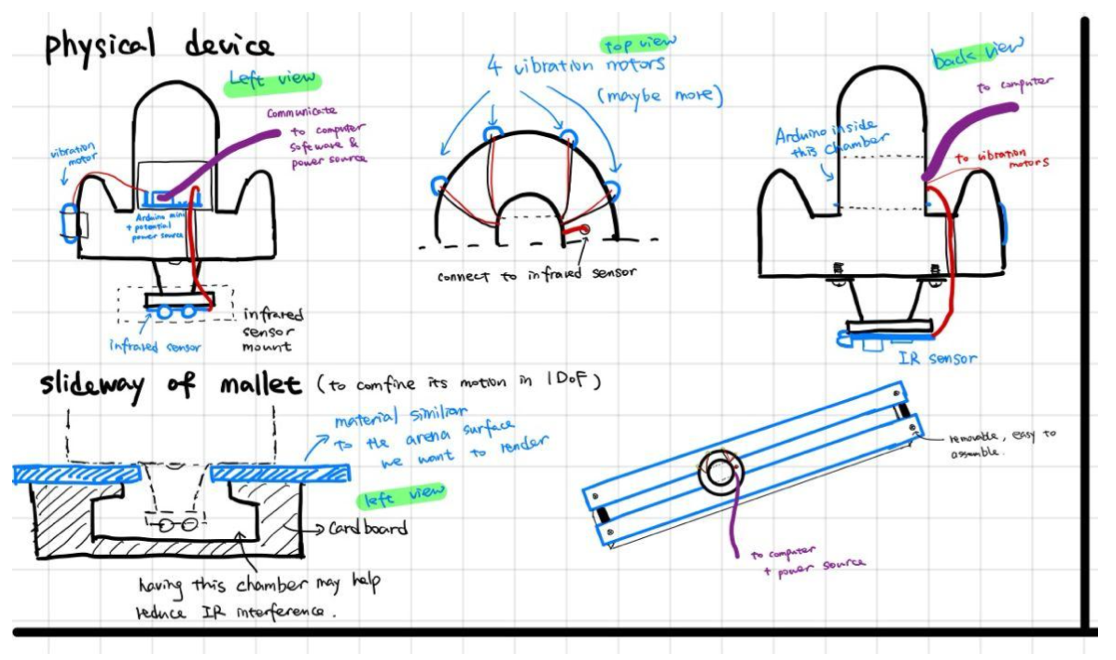
Figure 6. Initial Concept Design of Hardware.
However, after the ordered parts were delivered, the sensors are found to take more space than expected because of the pins and ports that "stick" out from the main board, so it is difficult to give more clearance inside. Therefore, we made a new design for the mallet, which is a shell which would have everything properly mounted inside, which is shown in the picture below (Fig 7).
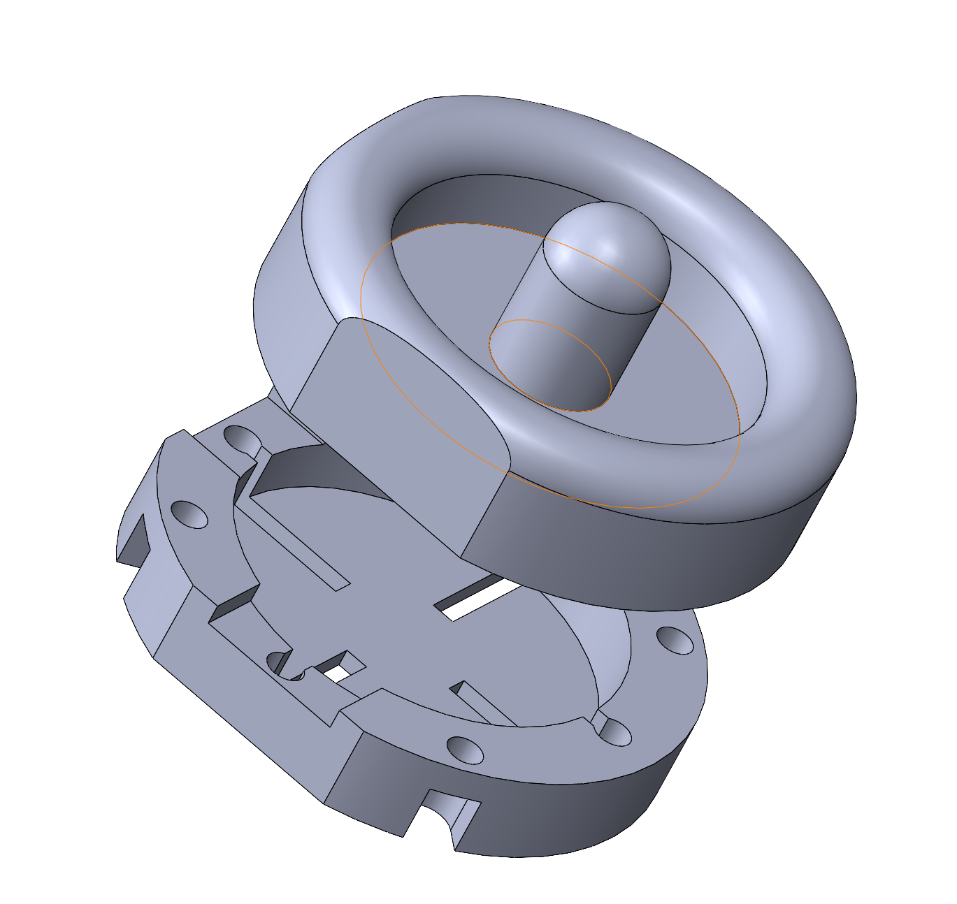
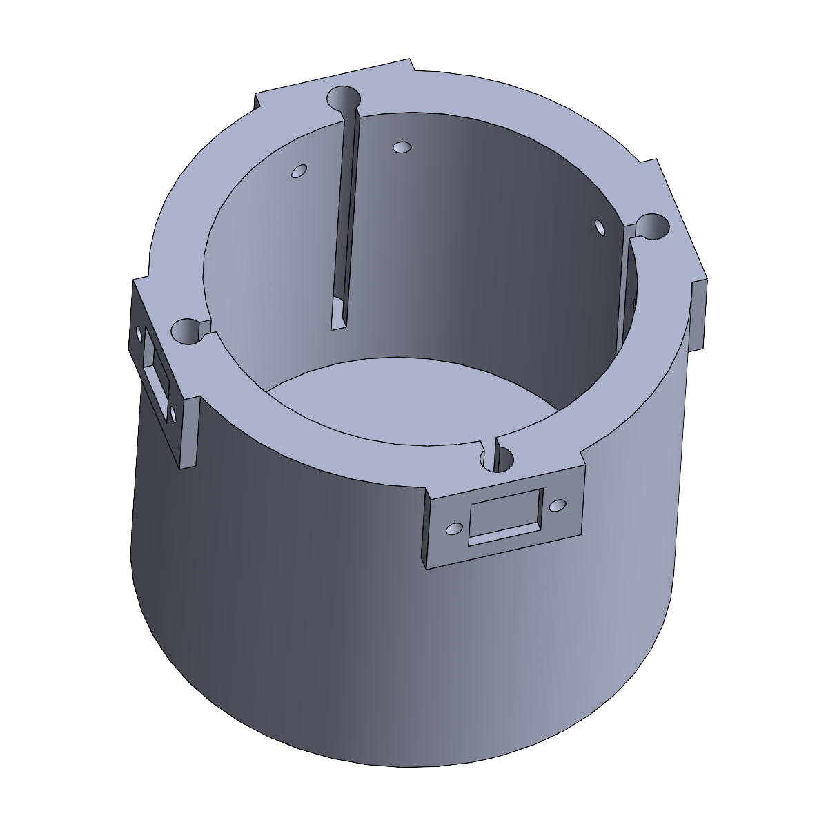
Figure 7. CAD Model of the Mallet (1st Design Iteration).
All the wires will be sorted out in a tidy way and directed to outside the mallet (the Arduino board sitting on a table and connected to a computer). Two IR range sensors will be installed on the sides of the outer well with a 90 deg angle so that the 2D mallet position could be defined. More design iterations will be produced if necessary, which depends on how smooth these components are incorporated. At last, we will put a 3D-printed simple cover on it to hold the sensors under after the design is finalized. Shortly we will use the resources in the Product Realization Lab (PRL) to build an arena in which the virtual game will finally be played in and two horizontal grooves on which the users give the mallets 1-D motion.
Checkpoint 2
Goals achieved for checkpoint 2
May 23rd: Rendering environment setup completed
May 24th: Circuit design finalized and two arenas built
May 25th: Device interaction code (C# in Unity) and sensor data collection code (Arduino) ready to use
May 26th: Mallet CAD model finalized and all 3D-printed parts ready
May 27th: Overall assembly finished and ready to play
Rendering environment - Unity game engine
For starters, we worked on building a virtual environment using the game engine Unity (Fig 8). The game will be played on a surface that looks exactly like a real air hockey table (Fig 9). There will be two mallets and one puck, and two red boards are placed on each side to represent the goal line. Users will feel vibration from the motors installed on the actual mallets. All collisions are correctly defined in Unity, including the puck hit by a mallet, the puck bouncing off from the playground edge, a mallet hit the playground boundary, and two mallets running into each other. The range of the virtual positions that mallets could reach are mapped according to the dimension of two identical physical arenas (Fig 10, Fig 11) made from acrylic glass and cardboard. A soundtrack is imported into Unity so that it generates a sound whenever a collision happens, which helps create a realistic game experience. We let Unity reset the puck to the playground center after a user scores a goal.
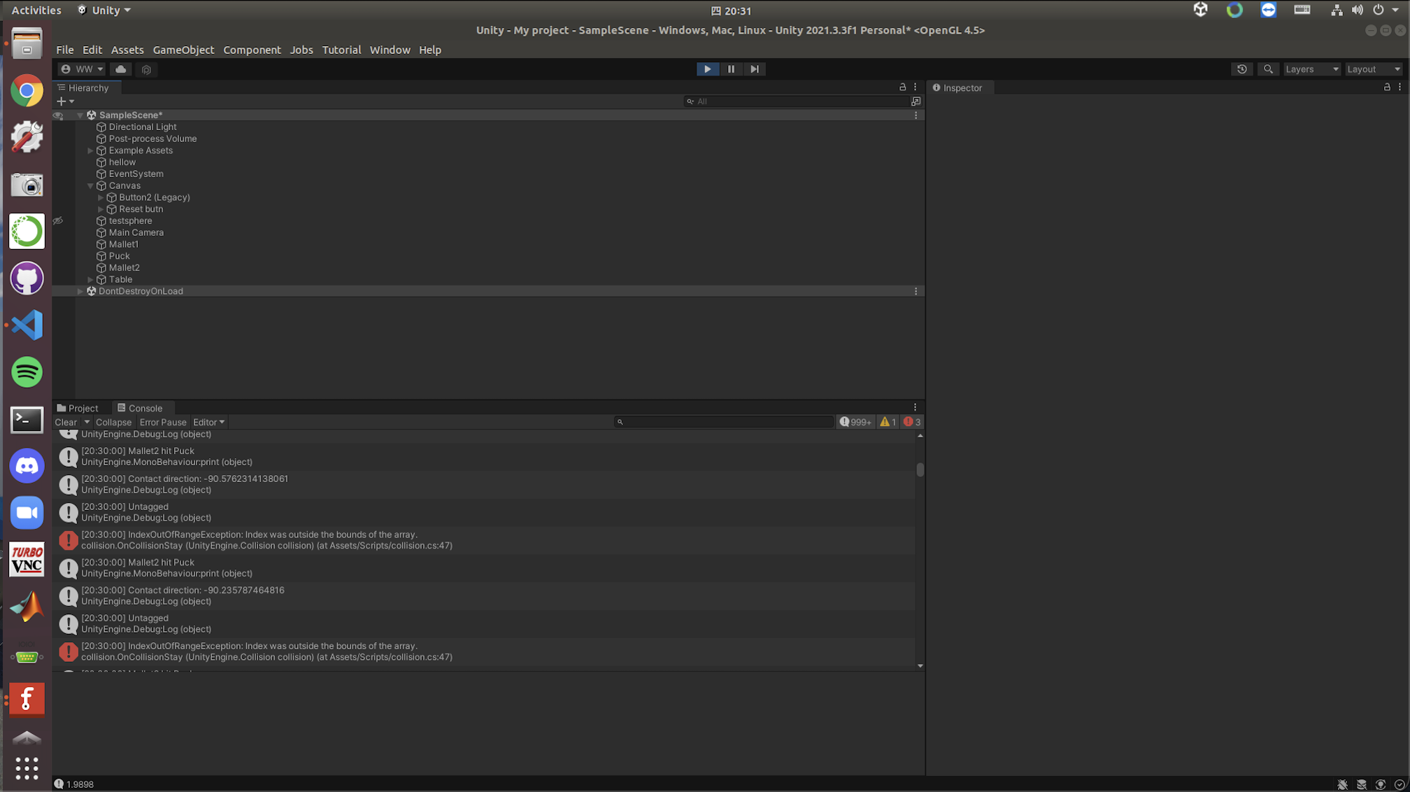
Figure 8. Unity user interface.

Figure 9. The virtual playground generated by Unity.
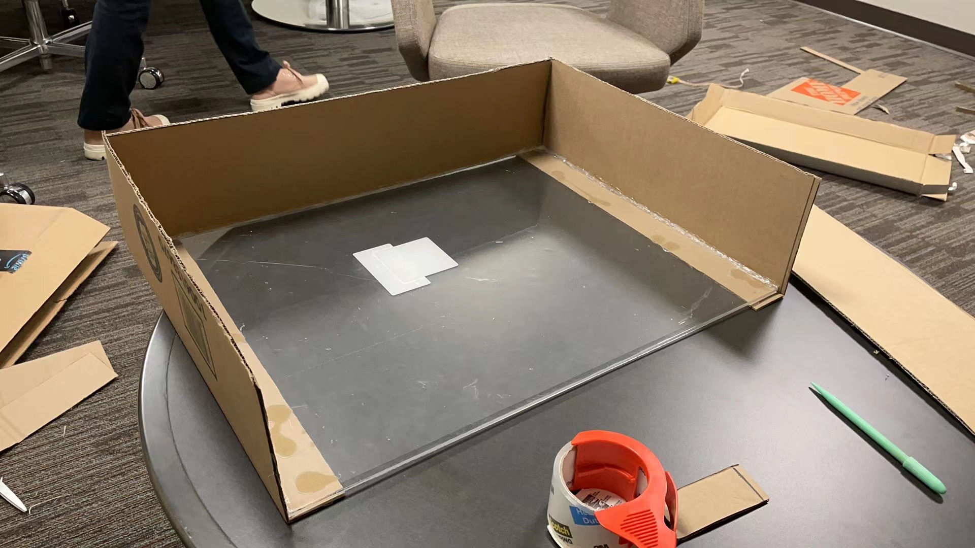
Figure 10. Arena One.
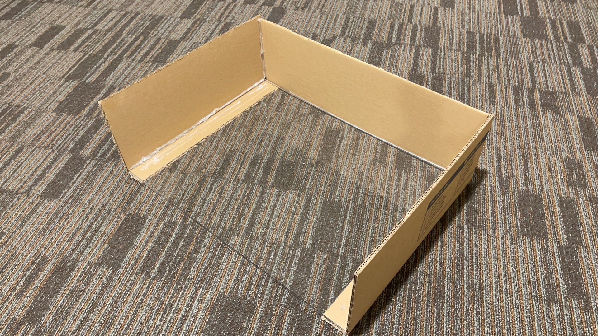
Figure 11. Arena Two.
Final device design & Interaction with software
When it comes to the hardware, we made a new design iteration for the mallet because the previous version, which is an outer shell which holds everything inside of it, is too bulky to actually be felt as a mallet. Accordingly, we made a new design which consists of a base cover and a handle top (Fig 12). Two IR range sensors VL53L0X are perpendicularly mounted in notches on two adjacent sides, so that the mallet position could be defined by distances to two sides of an arena. As for the circuit, we made a design using Fritzing (Fig 13). It is essentially an integration of the Arduino Nano board, two IR range sensors, and four MOSFETs that prevent current/voltage overflow. The base cover holds the breadboard, the Arduino Nano board, and all the connected jumper wires inside (Fig 14). Two wires connected to a function generator and the thick Arduino cord are directed out through the handle top opening and taped together (Fig 15).
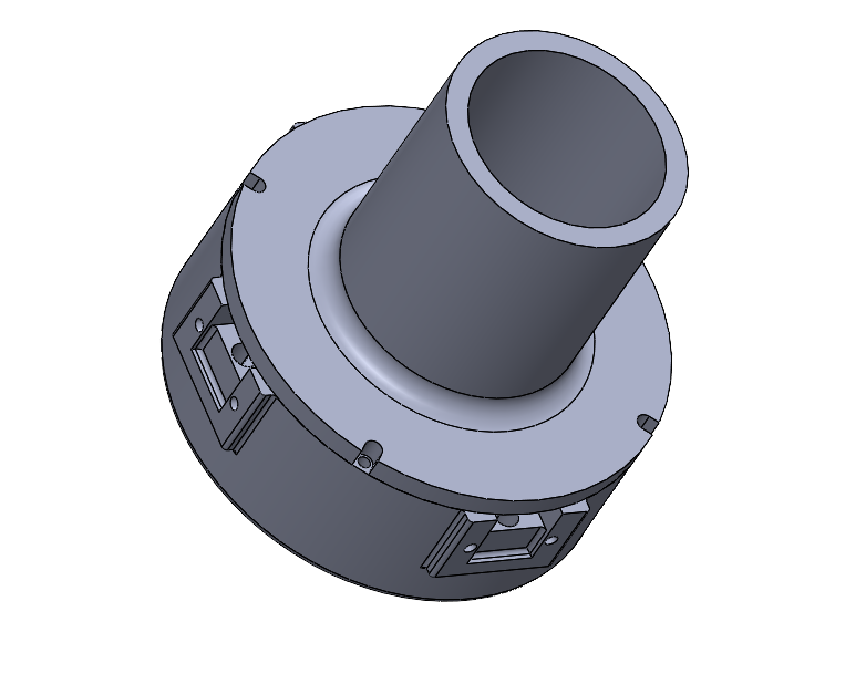
Figure 12. Finalized CAD assembly of a mallet.
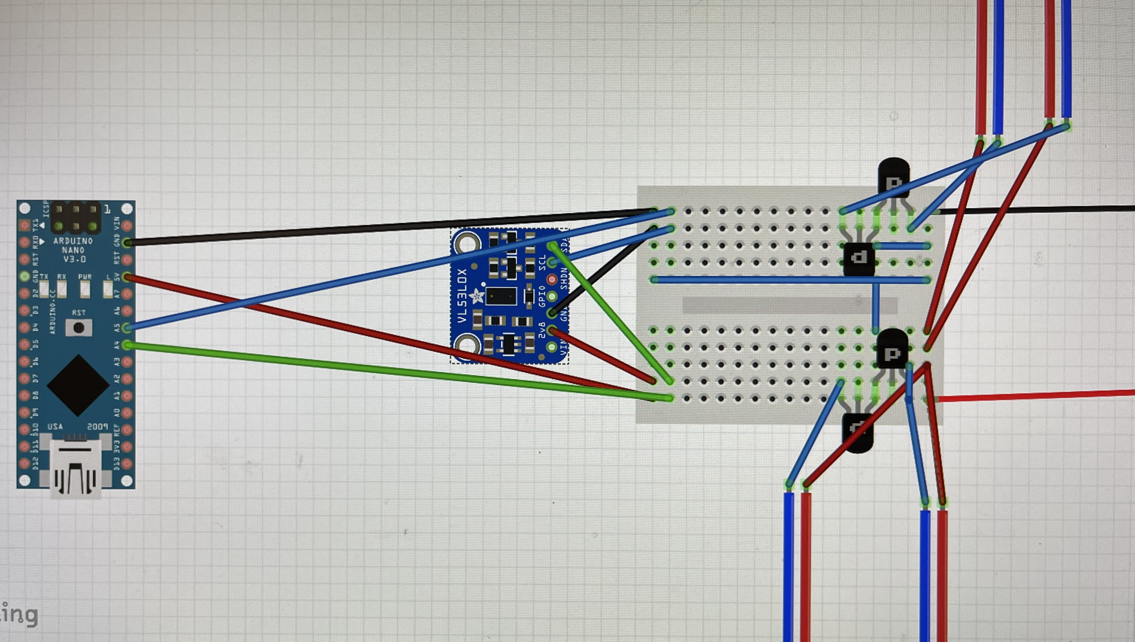
Figure 13. Circuit design in Fritzing.
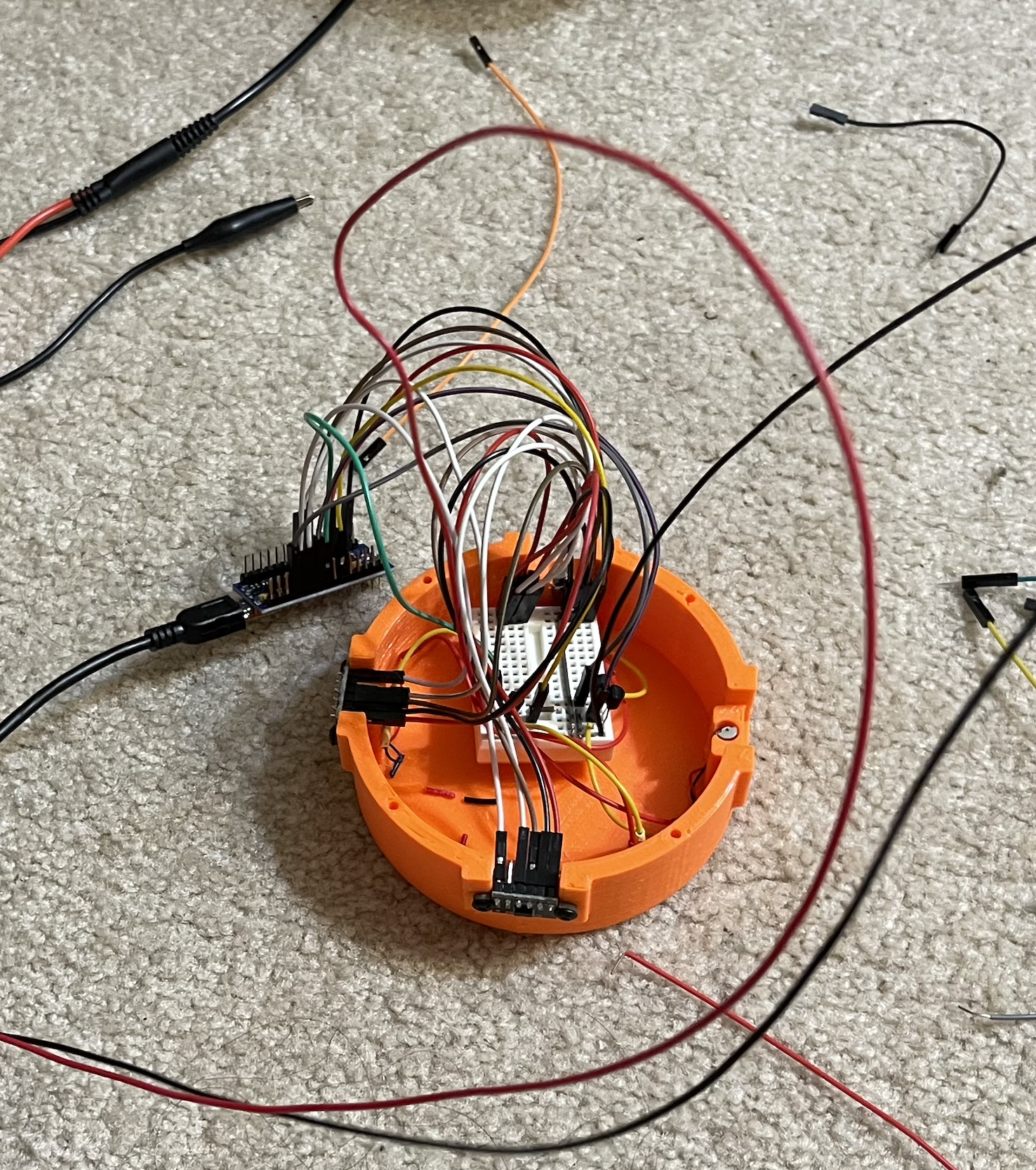
Figure 14. Base cover with components fit inside.
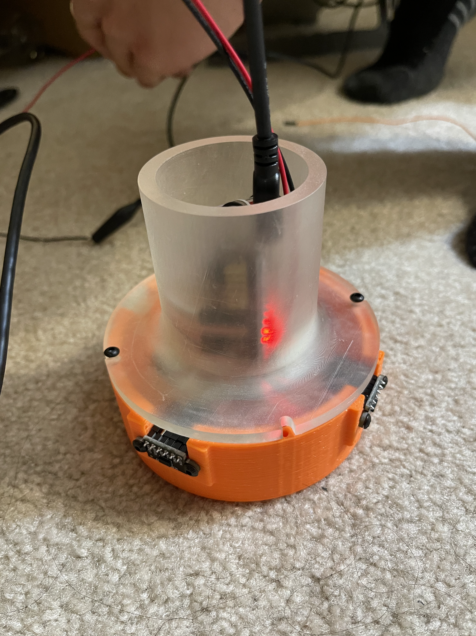
Figure 15. One assembled mallet.
Preparation for demo
Up to this point, we have built a fully functional prototype of a 2-player interactive air hockey, which demonstrates smooth performance in operation and decent realism in terms of haptic rendering. Here is a picture of the whole setup (Fig 16). Subjectively telling, it has a satisfying resemblance to the experience people usually get on a real air hockey table (future work and potential improvements will be discussed in the final report). We will paste a felt bad to the bottom surface of each mallet before the demo, so the mallet sliding won't scratch the acrylic glass. Below is a preliminary poster we are making for the demo day (Fig 17). Here is an example video: https://www.youtube.com/shorts/4y8mk9GSjRA?feature=share (we will retake a better one shortly).
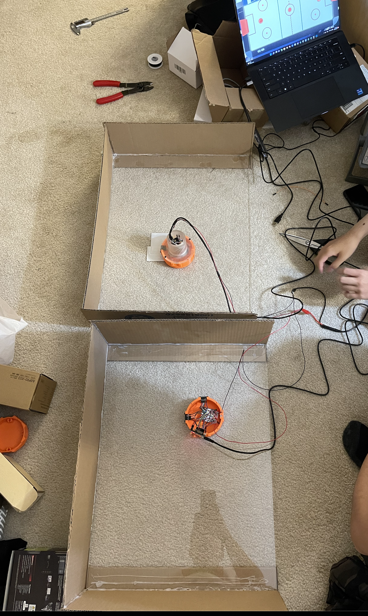
Figure 16. Overall setup.
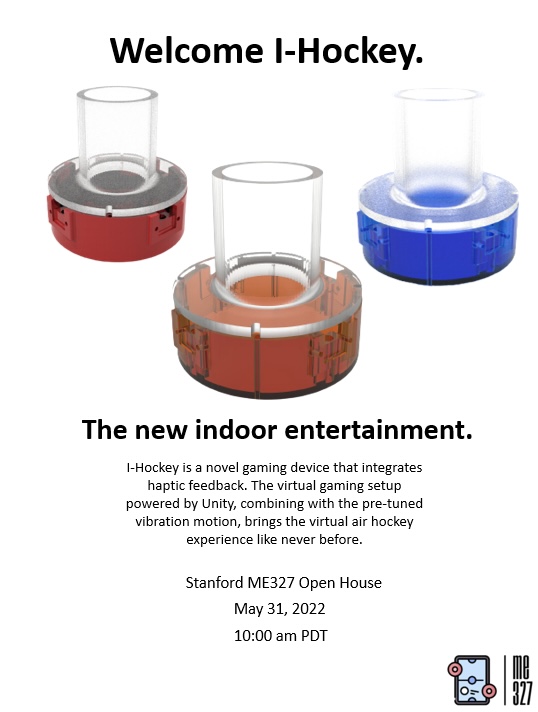
Figure 17. Demo day poster.