

Group 14
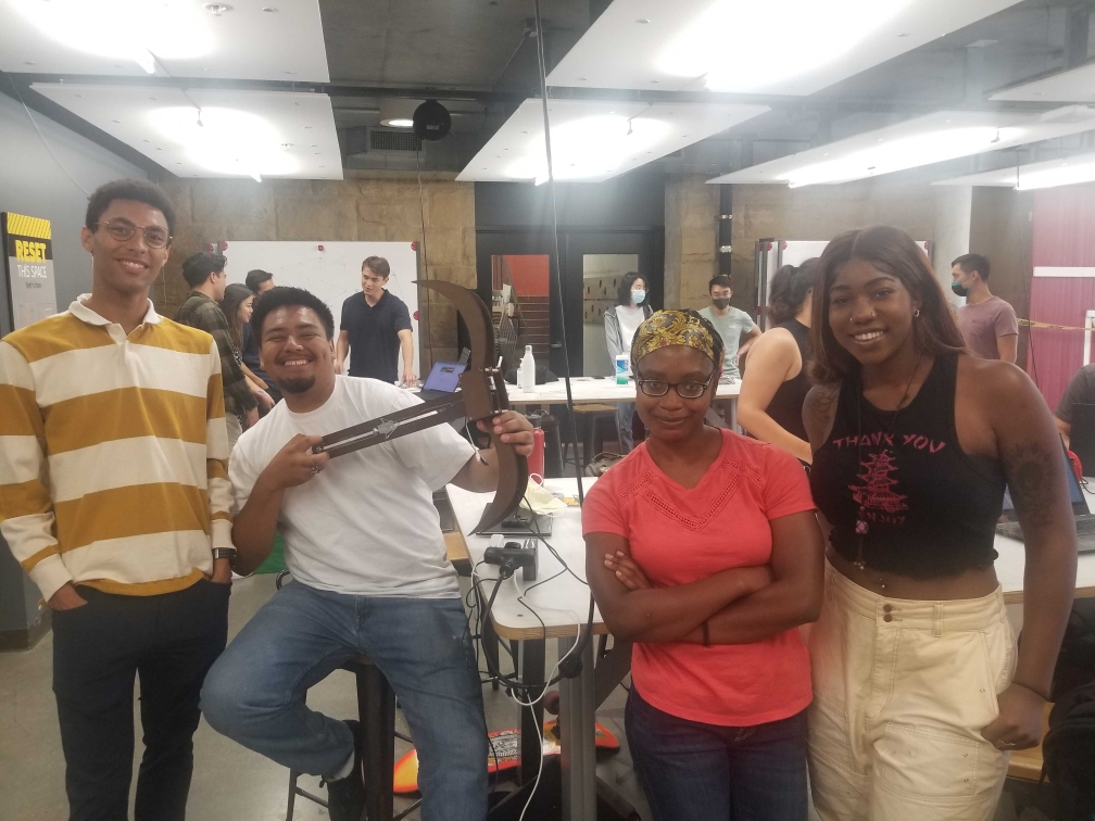
Marco hoists the bow-and-arrow
after a successful demo day.
Development of a Bow-and-Arrow Haptic System
Project team members: Alexa Davy, Elizabeth Childs, Marco-Antonio Vasquez, Miles Smith
The goal of this project is to demonstrate how a bow-and-arrow system could be rendered and simulated using relatively low-cost hardware and materials to demonstrate an understanding of how motors can be used to provide haptic feedback. The bow-and-arrow manufactured primarily focused on the motion and trajectory of the arrow with respect to the bow, which can be thought of as the frame. The main challenges when implementing and testing the bow-and-arrow were caused because there is little feedback indicating how the shot can be improved to get closer to the target. Despite the lack of trajectory feedback, most users were able to hit the target with some degree of accuracy and seemed to enjoy the interactive nature of the bow-and-arrow.
Give a one-paragraph description/summary of the project, which includes information like the motivation for the project, the goals of the project, and the resulting implementation and success of the project.
On this page... (hide)
Introduction
The motivation for this project is to develop a bow-and-arrow system that integrates haptic feedback controlled by an Arduino to simulate the motion of an arrow. This system was designed to integrate concepts in controls, mechanical design, and haptics into an integrated mechanism to demonstrate how the motion of a bow-and-arrow could be virtually simulated.
The approach of this system is to develop a mechanical bow that is connected to an arrow and controlled by a motor to simulate the restoring force of the bow's string when the arrow is displaced. The system has two degrees of freedom: angular position of the bow and displacement of the arrow. This approach allows for position and velocity estimation of the arrow so that the trajectory of the arrow can be estimated, which allows for the arrow position to be calculated as it approaches a target.
Background
Many different approaches to simulate the use of a bow-and-arrow have been explored. Training devices have aimed to correct user/bow interactions or accurately represent the use of a bow-and-arrow without the having the necessary range of actually shooting one. We aimed to focus on the resultant simulated motion of the arrow while providing the user with proper bow restorative force resistance.
As a start to studying bow-and-arrow user feedback, human-generated haptics have been explored. Self-haptics, although simple, prove to be quite effective as a user�s own two hands can be used to simulate the experience of using a bow-and-arrow while simultaneously viewing convincing visuals [1].
One example of a previous bow-and-arrow haptics device mimics the weight and size of the bow and responds to the user�s pull distance to generate a responding force. Τhe issue with this specific example is that the weight distribution does not agree with that of an actual bow, so an experienced archer would likely find this simulation inauthentic [2].
In an effort to improve performance, a training haptics device was designed to correct user posture by using not only visual aids but audio feedback as well [3]. This design was more lifelike than the previously mentioned approach but was much more complicated and required sensors to be worn in addition to the ones implemented in the haptics device itself.
Unlike these approaches, we hoped to design a bow-and-arrow haptics device that more accurately simulated the motion of the arrow based on user input while focusing less on the verisimilitude of an authentic bow.
Methods
- Duron
- MPU 6050
- Hapkit Kit assembly
- 4 Wooden Dowels
- 5 lb steel wire
Hardware design and implementation
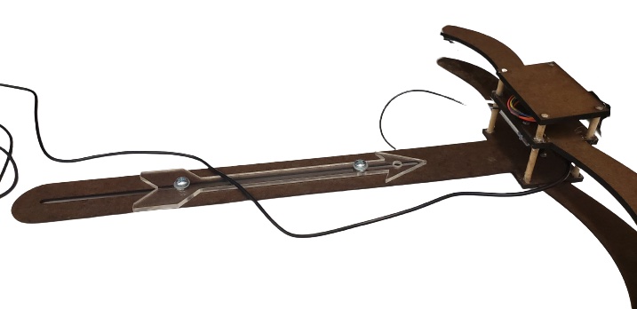
To recreate the haptic bow and arrow, laser cut the duron according to the dxf files (see files section). The arrow piece should be laser cut out of acrylic.
Using screws and nuts, attach the "bow body scaled down for motor" piece together with the "slot slide 4." The "slot slide 4" piece should be on top.
Attach the Hapkit motor to the �bow body scaled down for motor� piece, with the screws and washers going through �slot slide 4.� This is similar to attaching the motor in the Hapkit Assembly)
Attach the Hapkit Neoprene tube to the magnet holder and push the holder onto the motor shaft (similar assembly as the Hapkit). Glue the magnet into the magnet holder. Tie the cable around the neoprene tube.
Using the two holes at the back of the arrow, bolts, washers, and locknuts, connect the arrow to the �slot slide 4,� with the arrow pointing up at the motor.
Wrap the cable around the Neoprene tube 5-10 times, and tie it to the hole at the front of the arrow. Secure with duct tape.
Attach the hapkit to the �bow body scaled down for hapkit� piece, ensuring the A5 pins are accessible via the cutout.
Using the dowel rods and hot glue, connect the �bow body scaled down for hapkit to the slot slide 4 so that the hapkit hovers � cm away from the magnet.
Using foam tape from the Hapkit assembly, connect the IMU (pins closest to A5 rail). Attach the IMU to the hapkit in the following way: Vin to 5V GND to GND SDA to A4 SCL to A5 ADO to GND
Finally, connect the �top plate� to cover the IMU with the hot glue and dowels. Trim off the rest of the wooden dowel.
Connect the motor alligator clips to the motor. Note, the alligator clip farthest from the A5 rail should connect to the red dot connection on the motor.
System analysis and control
The arduino and processing code provide the system analysis to render the bow and arrow haptic and visual feedback.
The arduino code renders the tension in the cable as a spring. The farther back the arrow is pulled, the greater tension in the wire. When the arrow is pulled all the way back and released, the arduino sends the velocity and vertical angle over the serial port to processing.
The processing code takes in the velocity and angle, and using the SUVAT kinematic equations, calculates the location of the arrow on the target.
Demonstration / application
Connect the Hapkit power to the outlet, and the micro-USB to the computer. Open processing, and hold the hapkit still for calibration. Hold the bow as typical and draw the arrow. Release, and see the location of the arrow on the target.
Results
Based on user experience and testing, the mechanical bow-and-arrow system designed does intuitively seem like a bow-and-arrow, but there are a few challenges in the control system and visualization that could make the arrow shooting experience more realistic once improved. One of the main challenges is that the visualization developed was not very intuitive to the average person because the only indicator of where the arrow lands after being launched is the change in position of a small dot on a target. The dot was a solid indicator for the result of the launch but provided no feedback on how the user should correct their launch to be closer to the bullseye on the target. Since there were two degrees of freedom, determined by the angle of release and the exit velocity of the arrow, it was unclear which should be corrected to make the shot more accurate and this led to significant variance when the arrow was tested.
The precision of the haptic system would probably be improved with a better IMU, to develop more accurate position estimation, and some design modifications to reduce the friction between the arrow and the guide rail that the motor pulls the arrow along when "launched."
Despite the trajectory of the arrow not being very intuitive, the bow-and-arrow seemed to receive generally positive reviews from users. Further, most people had reasonable accuracy once they had enough time to get adjusted to the system.
Future Work
Our design definitely has room for improvement.
For one, the IMU device is not very precise which makes angular estimation difficult. We would have also preferred to have used a better wire since the stainless steel wire in our design is rather weak and lacks pliability. Ideally, a nylon-coated, braided wire, similar to that provided with the Hapkit, would have been chosen.
Although the feel of the bow was not our main priority, a more ergonomic design would make our design more user-friendly as it would fit more comfortably in hand. As of now, the shape is slightly awkward to hold for testing.
In terms of safety, the fact that the motor must run constantly to keep the arrow/capstan system in tension is not ideal. This constant use causes the motor to heat up quite a bit rather quickly.
Lastly, we would also like to test out different visuals in our software program in order to keep the user more interested and entertained.
Acknowledgments
Here you can list any individuals or groups who helped you with your project. (e.g., another student in the class, a course assistant, or an especially helpful PRL TA). Optional, so delete this section if you aren't using it.
Files
- Bow and Arrow Assembly
- Total Cost Break-down
- Assembly Drawing
- Parts (DXF)
- Circuit
- Code
- Graphics (Processing)
- Hapkit (Arduino)
References
[1] Mengying Fang, C., & Harrison, C. (2021). Retargeted Self-Haptics for Increased Immersion in VR without Instrumentation. In The 34th Annual ACM Symposium on User Interface Software and Technology (UIST '21). Association for Computing Machinery, New York, NY, USA, 1109�1121. https://doi.org/10.1145/3472749.3474810
[2] Butnariu, S., Duguleană, M., Brondi, R., G�rbacia, F., Postelnicu, C., & Carrozzino, M. (2018). An Interactive Haptic System for Experiencing Traditional Archery. Retrieved May 23, 2022, from http://acta.uni-obuda.hu/Butnariu_Duguleana_Brondi_Girbacia_Postelnicu_Carrozzino_84.pdf
[3] G�bel, S., Geiger, C., Heinze, C., & Marinos, D. (2010, May 1). Creating a virtual archery experience: Proceedings of the International Conference on Advanced Visual interfaces. ACM Other conferences. Retrieved May 23, 2022, from https://dl.acm.org/doi/pdf/10.1145/1842993.1843056
Appendix: Project Checkpoints
Checkpoint 1
The main goal of Checkpoint 1 was to create sketches to develop a complete concept of the mechanical system we are attempting to design and an accompanying CAD assembly. Unfortunately, we were unable to create the CAD models because developing the mechanical design took longer than anticipated to develop a linear motion system connected to the motor and determine how to mount the motor, Hapkit, an Inertial Mass Unit (IMU), which we are going to use to measure angular position.
The mechanical system contains a bow, an arrow, and a linear guide rail to constrain the motion of the arrow to the horizontal plane and all of these components were designed to be manufactured using a laser cutter. In this system, the guide rail is secured to the bow at the center (which is the same location for the motor and Hapkit mounting). Then, the arrow is fixed to the guide rail using two screws so that the arrow can only move along the rail.
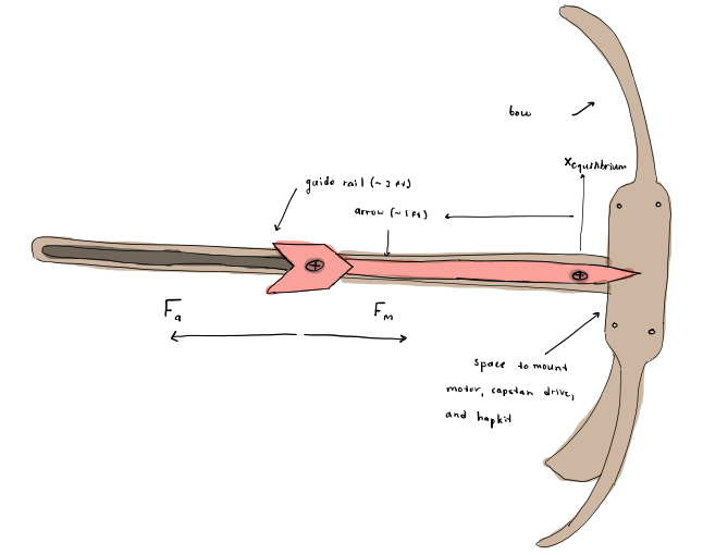
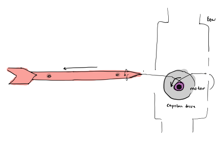
To measure linear motion a linear capstan system similar to the previously developed angular capstan system will be used. This system will measure position by monitoring the rotational change of a magnet connected to the motor shaft.
After working through most of the design the next steps are to develop the system as a complete CAD assembly and to manufacture and assemble those components, which will hopefully be completed in the next couple of days. Once the mechanical system is designed, then the control system for the motor and the visualization can be developed.
Checkpoint 2
The main goal for Checkpoint 2 was to create a functional prototype of the mechanical bow-and-arrow system and an outline of the Arduino and Processing code so that once the mechanical system is finalized the code would need to be calibrated to the system.
To outline the system design, prototype CAD models for the mechanical system were developed and fabricated. The prototype CAD models were then improved iteratively so that the motor and Hapkit could be mounted in the system and the magnets connected to both could be spaced adequately. The IMU was connected to the Hapkit using jumper cables and then secured to the mechanical system using adhesive.
A simulation arrow was also designed and loosely screwed onto the system. The goal for the arrow was to connect it to the motor shaft using a thin stainless steel wire cable, which still needed to be purchased. Once received the goal is to tether the wire cable to the arrow and the motor shaft so that the cable would be connected like a spool and would unwind as the arrow is pulled back and then could be wound up by the motor rotating in the reverse direction.
Once the wire cable is connected, the software can be calibrated. Once that is figured out the bow-and-arrow system should be ready for testing!