

Group 22

Electromagnetic Geometry Display
demonstration at the ME 327 haptics open house.
Electromagnetic Geometry Display
Project team member(s): Shuai Wu, Yilong Chang, Man Wu, Xinyi Liang
As the most current haptic devices require users to interact through handles and have a space limitation, we want to build a contactless haptic device generating a similar haptic display. The objective of this project is to create a haptic display of different terrain geometries. The geometries are generated by an array of seven coils, which produce electromagnetic field when applied current, with a permanent magnet attached to the users’ fingertips, the users can feel the repulsive electromagnetic force and thus the desired geometry with different combinations of activated coils. Hardwares include Arduino board and Mosfet to control the current in each coil. Eventually we were able to create five terrain geometries, and the users gave positive feedback on our haptic display and said they really feel the “mountains” and “valley”.
On this page... (hide)
Introduction
Haptic devices provide humans an effective way to interact with virtual environments or remote objects, laying the foundations for various application areas, such as virtual and augmented reality [2], surgical training [3], and assistive medical care [4]. Current devices are based on different actuation methods [5-6], including micromotors, pneumatics, electrostatics, and electroactive polymers, which generally exhibit limitations of complex and wired system design, high cost, poor portability, low bandwidth, or complex distributed actuation. Electromagnetic actuators [7] generate magnetic force under a continuous magnetic field in space, offering a robust solution for haptic applications with simple structure, wireless actuation, fast response speed, and smooth force distribution. Existing magnetically actuated haptic devices [8-9] rely on the separated stationary electromagnetic array and rigid magnets for generating a magnetic field and haptic sensation. Controlling the current in the electromagnetic coil can easily manipulate the reaction force (attractive or repulsive) on-demand. Thus, we design a simple system that offers a robust solution for haptic display with fast, selective, and wireless actuation, enabling reliable and effective haptic demonstrations for educational objectives. The system consists of arrays of seven electromagnetic coils being stationary on a flat surface and a permanent magnet rod held by the user. Repulsive forces from magnetic fields are generated as current runs through the coils. Thus, by specifically selecting the actuated patterns and applied currents in the coil array, we achieve a smooth 2D force distribution in a wireless way, mimicking the force feedback of a user touching rigid terrain geometries.
Background
Haptic/tactile display devices relying on electromagnetic control have been demonstrated through different magnetic actuation strategies. Xiong et al. designed a contactless haptic display that provides force feedback to a user when holding a magnet inside a huge electromagnetic coil. Force distribution within the giant coil from finite-element analysis guides current control of the coil for a preferred reaction force to the user when relying on the mixed reality for the haptic display [10]. Instead of having one enclosed space, Zárate et al. designed a tactile device with four-by-four pins that can be actively controlled by the electromagnetic coils beneath, switching between the low state and levitated state on a 2D plane for a distributed bumps display [11]. An alternative strategy relying on the magnetorheological fluid is also exploited by Rizzo et al. that uses distributed magnetic field to physically change the display from a fluid state to a semisolid state by applying a localized magnetic field 12, but this method suffers from the low resolution and less user-friendly due to the nature of the magnetorheological fluid. While the concept of haptic display with an array of electromagnetic coils is not new [13-15], we use a universal mechanical tester to characterize the reaction force between the electromagnetic coil and magnet. A special magnet arrangement is made with a rod-like geometry to let the user feel the maximized feeling of displayed terrains.
Methods
The overall system of the design consists of seven individually controlled electromagnetic coils arranged in an hexagonal array shape.
Electromagnetic coil
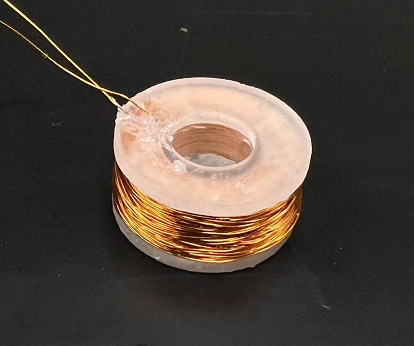
Each electromagnetic coil consists of the inner plastic core and the conductive copper wire that wraps around it. Plastic core is designed with inner hollow shaft diameter of 10.6 mm and outer circular edge diameter of 24 mm, which creates a hollow cylinder placeholder for wrapping wires.Please refer to drawings in File section for detailed information.The core is 3D printed using Foamlab with rigid resin and post-processed under 80 degree for 20 min to enhance its rigidity. The wires used in fabricating coils are 32 AWG (0.2019 mm diameter) copper wire. Wires are manually wrapped around the hollow shaft of the inner as tight as possible until it fills the hollow cylinder placehold and reaches to the circular outer edge shown in figure below. The resistance of each coil is measured using voltmeter.
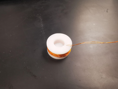
Single electromagnetic coil
Electromagnetic array
Seven electromagnetic coils with close resistance (ranging from 15 ohms to 17.5 ohms) are fabricated and assembled in an hexagonal like array shape through an array holder It is designed into hexagonal shape so that coils are closely packed together and overall resemble a circular pattern since repulsive force decays radially. The holder is 3D printed with Ultimaker with tough polylactic acid material. Coils with similar resistances are purposely placed together for the easiness of generating uniform repulse force at specific location and generating gradient force mapping across certain direction.
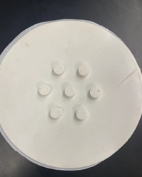
3D printed base for coil array
Characterize repulsive force from single coil
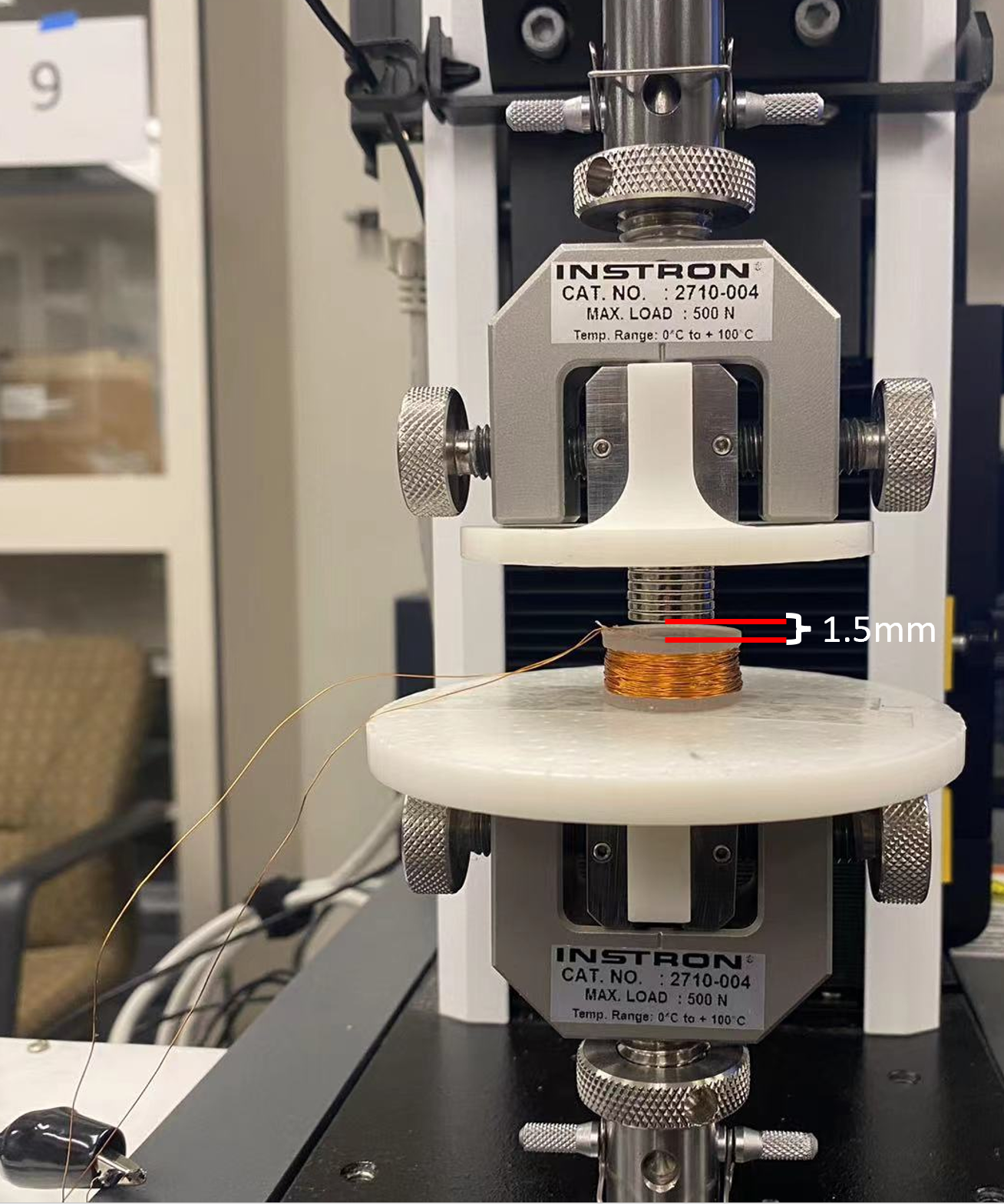
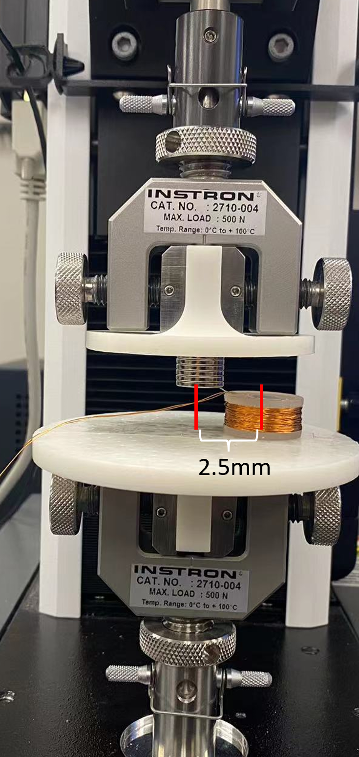
The repulsive force generated by a single coil along its radial direction at various current against a stack of 5 NdFeb circular magnets with diameter of 20 mm and height of 1 mm is measured using Instron machine and is plot using Matlab to obtain force mapping decay along the coil radial direction.
The experiment is conducted using an Instron testing machine with an electromagnetic coil placed at the bottom stage connecting to a power source and a magnet fixed at the top stage. The Instron machine is being set in tensile testing mode and zeroed when zero amps of current are applied. The vertical distance between the magnet and the top surface of the electromagnetic coil is fixed at 1.5 mm. Current is gradually increased from 0 A to 0.5 A with an incrementation of 0.1 A and corresponding force data are recorded. Initially, the magnetic and coil are placed with an aligned vertical axis, and the mentioned above testing is repeated as the coil is placed in the position that is 5, 10, 15, 20, and 25 mm horizontal distance from the center axis of the magnet to generated force versus radial distance data.
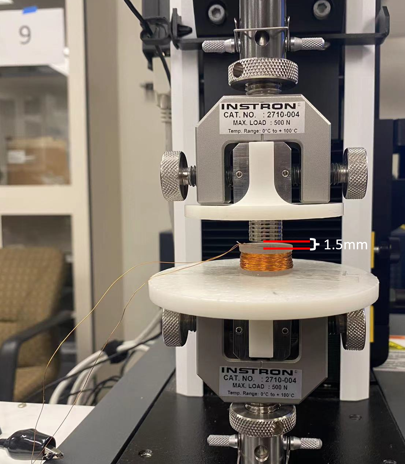
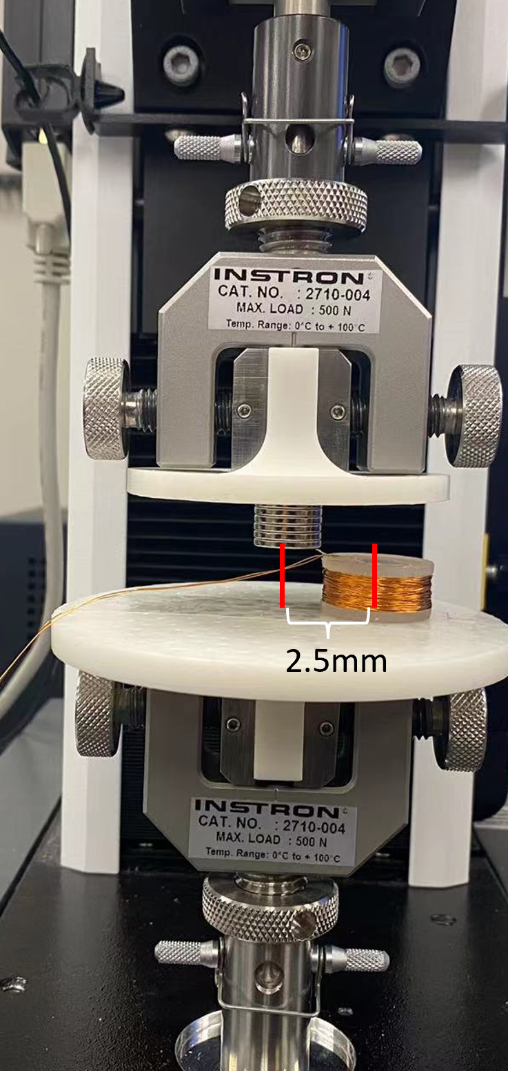
Characterization test setup
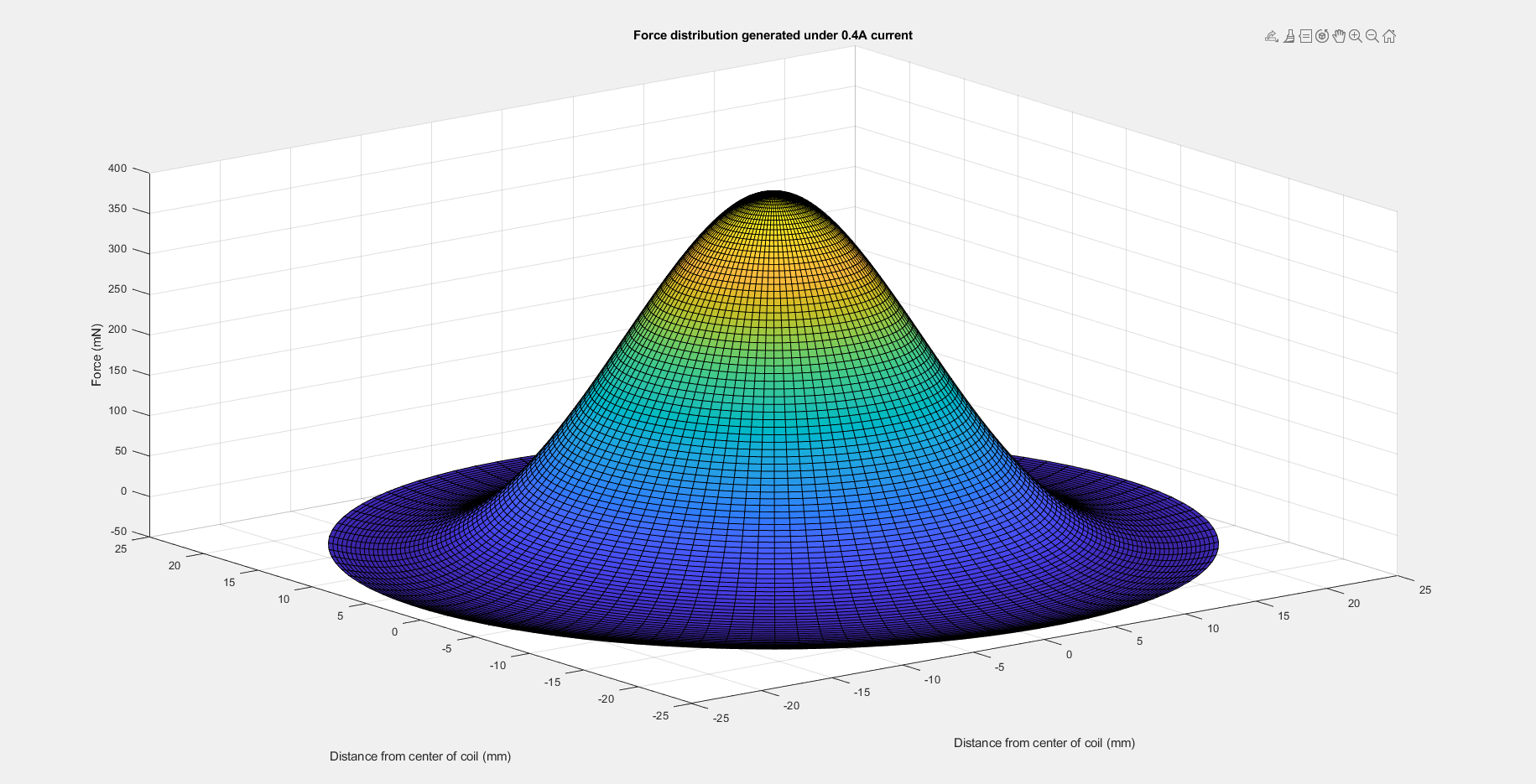
At a given current of 0.4A, the reaction force is the maximum when the coil and magnet are facing each other, and gradually decreases as the magnet moves away, reaching ~0 N at a distance of 20 mm.
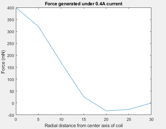
The discrete data points are fitted by a 4-th order polynomial function to get a smooth “Force versus Off-axis distance” function. As the structure is axisymmetric, the obtained 2D function can be extended to a 3D kernel function. For the 7-coil system arranged in a compact way, once the current in each coil is decided, the reaction force on the magnet is the summation from seven coils in total. Based on geometric relations between the magnet to the coils, the force mapping across the 2D plane can be decided.

Force mapping generated by electromagnetic array
The repulsive force mapping is generated through the assembly of individual coil force distribution. With selectively actuated coils, repulsive forces are generated by each activated coil and are summed at every location inside the coil array to form force mapping. For example, by deaucated coil 2(center coil) while activating others, the force mapping displays a valley map in which the repulsive force remains large at the periphery whereas the center has zero or even attractive force . Additionally, by only actuating the center coil, a force map that represents a bump is generated shown in figures below. Repulsive force is the largest at center and decades to zero at the array edges. The amount of current running through the coil is also tuned which opens up a wide range of possibilities for force mapping generation. For example,by supplying current of 0.1, 0.3, and 0.5 amps on coils 5, 2, and 4( mid three horizontal coils) respectively, a force distribution that represents a step in which repulse force graduate increases horizontally along the midline is formed. With seven coild implemented in the array and possible supplying current varying from 0 to 0.5 A, the programing ability of fore mapping is expansive. To better demonstrate the functionality and ideas of the design, we decided to choose five most distinctive patterns for users to test on demo day.
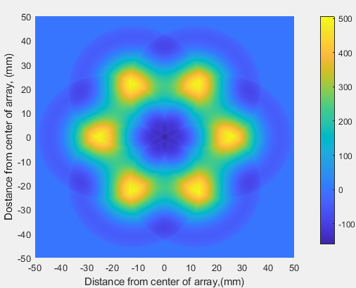
Force mapping represents a valley
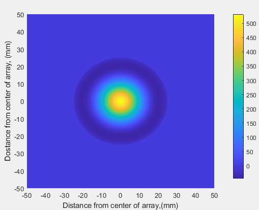
Force mapping represents a bump
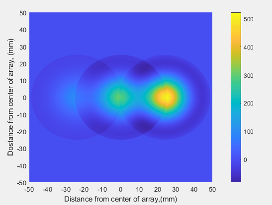
Force mapping represents a step
Mechatronic implement
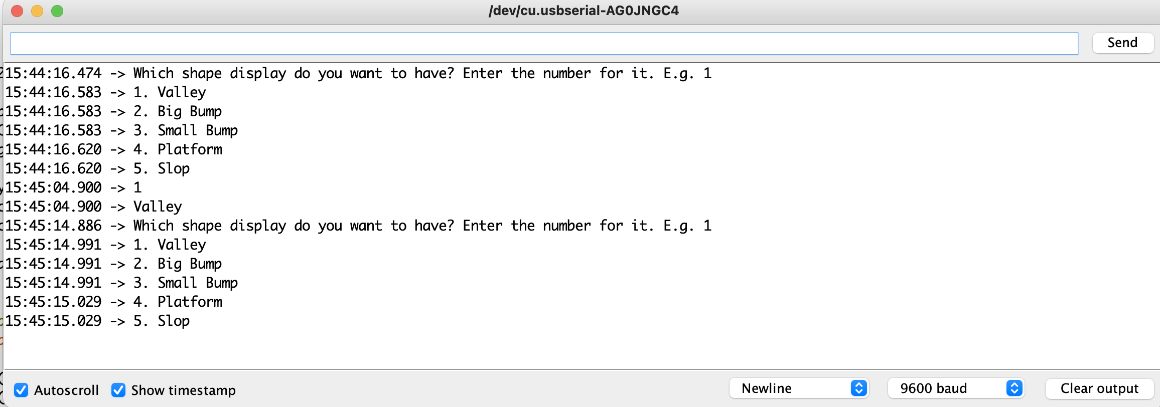
In order to display five different geometries with seven coils, the following flow chart is used as the general control scheme. Each geometry is associated with a number from 1 to 5. After the user enters a number, the algorithm first checks whether it is a valid input. If not, it asks the user to have a new input. After this, the algorithm activates specific coils with pre-determined current. Finally, the user can feel the geometry. Due to safety concerns, each geometry only displays for 8 seconds as longer activation time will increase the coil temperature significantly.
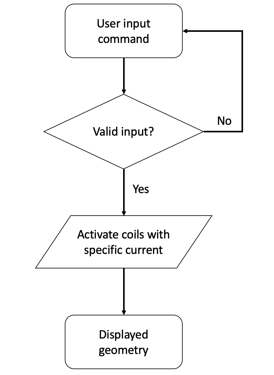
Algorithm flow chart
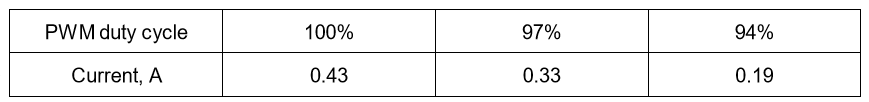
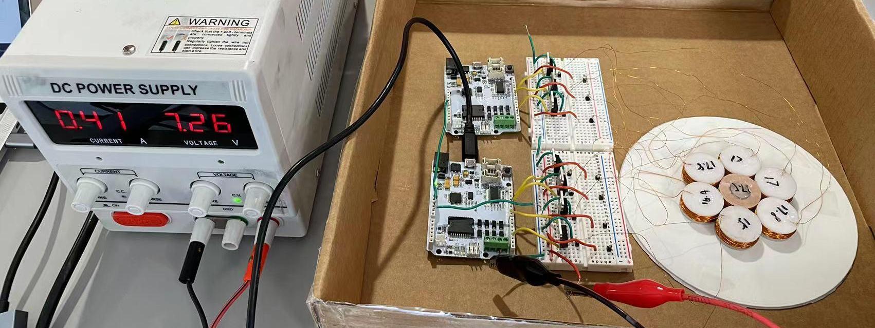
Each coil is controlled separately with an open-loop circuit shown below. To generate a strong enough magnetic field, N-channel Mosfets are used as electronic switches to pass relatively large current(up to 0.5A per coil). The drain pin of Mosfet is connected to a 8V power supply which can generate up to 10A current. An output voltage from Arduino is fed into the Gate pin. The Source pin is connected to the coil then with the Ground. When the Arduino outputs a 5V, the Mosfet is on and the current can pass through. While it is off when Arduino outputs 0V. In order to get different equivalent current, PWM is used to control the Arduino input to Mosfet at a frequency of 3.9kHz. To get such a high frequency, only pins 3, 9, 10, 11 on each Arduino board can be used. As a result, we need two haptic board Throughout testing, the equivalent current is not proportional to the PWM duty cycle listed in Table 1.
Table 1. PWM duty cycle with corresponding current through coil
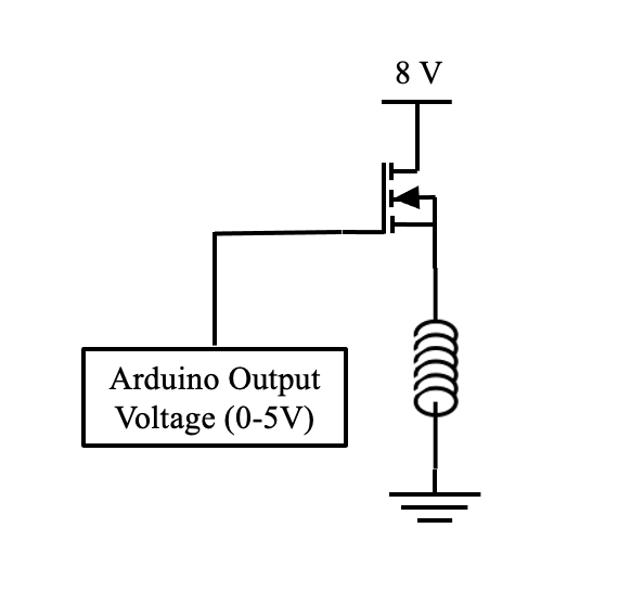
Circuit schematic
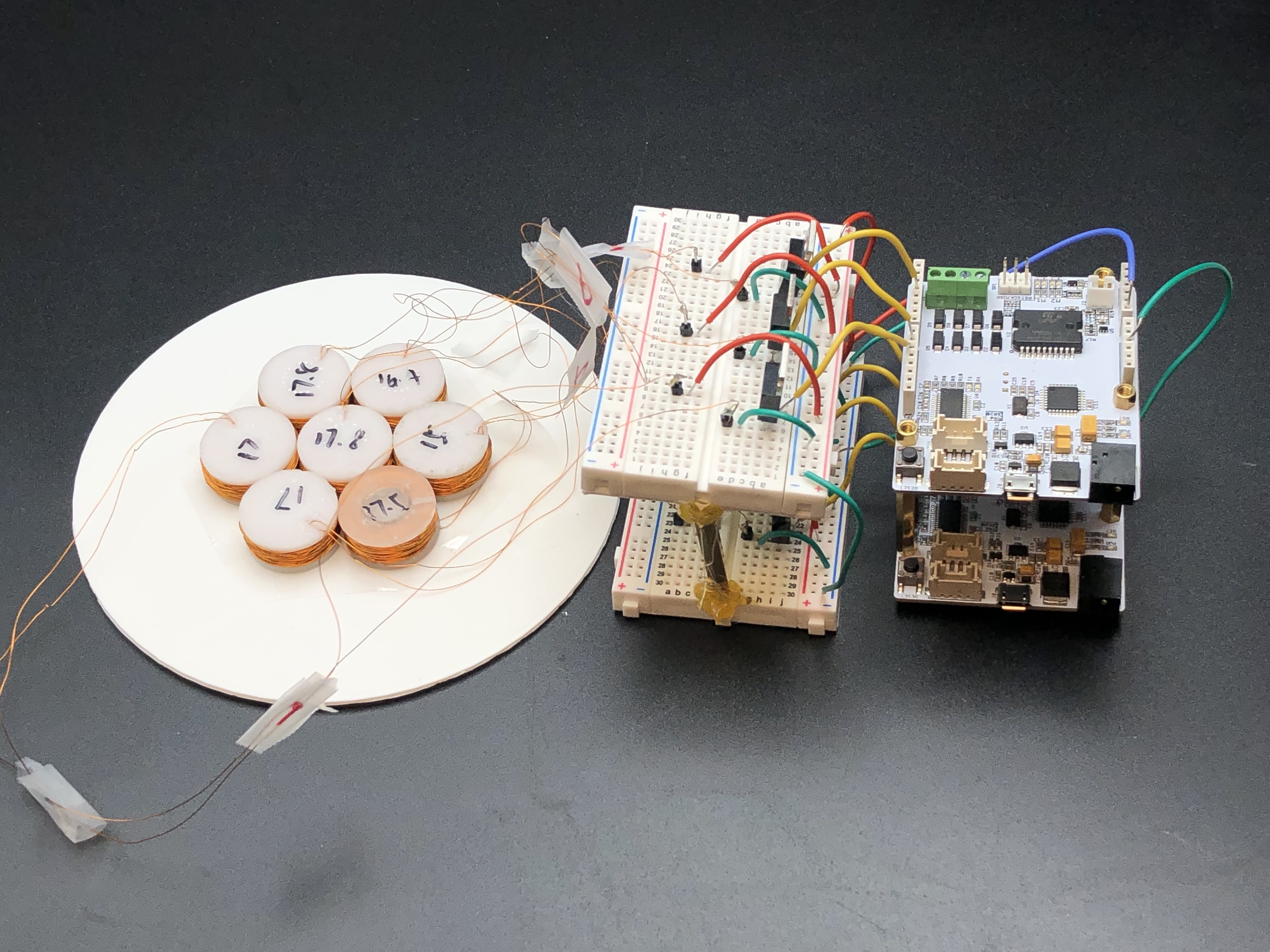
Assembled hardware system
Results
In the open house, there were 20 users who tried our electromagnetic haptic device, all of whom were students and teaching faculties from ME327 or other engineering fields. Almost all of them gave positive feedback on our haptic display and said they really do feel different terrain shapes like a mountain and valley. The display was reflected as stable and noise-free.
The device was originally set up with coils hidden under a non-transparent PLA flat plate, which intended to make a two-degree-of-freedom system allowing users to move in the same altitude, for the first user. Although we marked the coils’ region, users cannot understand how to interact with our haptic device when it was first introduced to them. Therefore, the first user cannot give strong feedback on the device. We then flipped the device to show the users how coils are arranged and made more sense for users to understand where to feel the haptic forces.
Additionally, without guidance, 55% of the users do not know how high above the coils to feel the haptic display as they do not have previous experiences of how large the magnetic field can be generated by those coils. There were 3 users moving magnets high in the air that they only felt very little repulsive force, while 8 users attached magnets so tight on the coils’ surfaces that the forces they applied are larger than the electromagnetic forces and cannot feel encountered displacement. Also, 25% of the users do not follow the desired moving pattern to interact with our haptic display. There were 2 users removing the magnets immediately after they felt force on a point, while 3 users stuck to one coil that they wanted to feel, the center coil for the valley mode for instance. However, as we did not perform attractive force, there was no force by the center coil and thus the users could feel nothing.
Future Work
To better test the performance of electromagnetic displays, one more experiment should be done. We want to explore the minimum magnetic field intensity difference the user can distinguish. In order to get this information, the users will be asked to keep their hand still with a permanent magnet sticking to their index finger above one coil. While gradually increasing the current through the coil, we will wait until when the users notice a changed force for the first time. We will repeat this experiment by increasing the current with different speeds to rule out how this affects the result. With this information, we can generate a smooth haptic display by manipulating the shape and size of each electromagnet to ensure that the fluctuation of magnetic field strength over space is not noticeable.
As the current coil diameter is relatively large, the magnetic field decays rapidly in radial direction and reversed field direction at the edge, causing low resolution and discontinuous of the repulsive force while interacting with the permanent magnets. We want to do more experiments with smaller coils to increase the resolution, and smaller differences between the coil size and magnet size in order to reduce the effects of electromagnetic field decay. In addition, more arrangement and geometry of the coil array can be explored. For instance, a multi-surface spherical stand can be created to attack coils on it. Also, we can attach multiple magnets on the user's hand to experiment how multiple haptic displays on hand can affect the human perception of the virtual shape.
Throughout the open-house demo, we found several ways to improve the electromagnetic displays. First, without any visual aids, the users have no clue of how and where they should move the magnet to feel the geometry, even though we explained verbally and specified the working area. The users had much better understanding when they could see where the coils were. So, we believe that having a visual display of the geometry displayed and where the user is can greatly improve the user experience. To do this, multiple position sensors should be attached to the user’s index and magnet to determine the position in 3D and the orientation of the magnet. Even at the same position, different orientation of the magnet can result in different force felt by the user.
Second, for all the issues caused by unfamiliarity of how to interact with our haptic device, a short tutorial can be created and shown to the users before their first attempt. This tutorial will teach the user how close they should place the magnet to the coils and what is the movement pattern they should have, etc.
Third, the open-loop circuit can only generate repulsive force without any calibration, which limits the geometries that can be displayed. To solve this problem, the H bridge circuit should be combined with the current circuit to have both attractive and repulsive force. To stable display, hall effect sensors can be implemented to detect the magnetic field and through a feedback loop to have better control.
Acknowledgments
We acknowledge the help from Dr. Qiji Ze on designing the electromagnetic coils.
Files
All of our files can be found in this zip file: Attach:ME327_group22.zip
which includes:
1. Arduino code for the first board: board1_control.ino
2. Arduino code for the second board: board2_control.ino
3. coil model for 3D printing: Coil.SLDPRT
4. coil base model for 3D printing: Array.SLDPRT
5. Electromagnetic field mapping: force_mapping.m
References
[1] Culbertson, H., Schorr, S. B., & Okamura, A. M. (2018). Haptics: The present and future of artificial touch sensation. Annual Review of Control, Robotics, and Autonomous Systems, 1, 385-409.
[2] Sherman, W. R., & Craig, A. B. (2018). Understanding virtual reality: Interface, application, and design. Morgan Kaufmann.
[3] Huber, T., Paschold, M., Hansen, C., Wunderling, T., Lang, H., & Kneist, W. (2017). New dimensions in surgical training: immersive virtual reality laparoscopic simulation exhilarates surgical staff. Surgical endoscopy, 31(11), 4472-4477.
[4] Ozioko, O., Karipoth, P., Hersh, M., & Dahiya, R. (2020). Wearable assistive tactile communication interface based on integrated touch sensors and actuators. IEEE Transactions on Neural Systems and Rehabilitation Engineering, 28(6), 1344-1352.
[5] Pacchierotti, C., Sinclair, S., Solazzi, M., Frisoli, A., Hayward, V., & Prattichizzo, D. (2017). Wearable haptic systems for the fingertip and the hand: taxonomy, review, and perspectives. IEEE transactions on haptics, 10(4), 580-600.
[6] Ho, T. Y. K., Nirmal, A., Kulkarni, M. R., Accoto, D., & Mathews, N. (2022). Soft Actuator Materials for Electrically Driven Haptic Interfaces. Advanced Intelligent Systems, 4(2), 2100061.
[7] Abbott, J. J., Diller, E., & Petruska, A. J. (2020). Magnetic methods in robotics. Annual Review of Control, Robotics, and Autonomous Systems, 3, 57-90.
[8] Zhang, Q., Dong, H., & El Saddik, A. (2016). Magnetic field control for haptic display: System design and simulation. IEEE Access, 4, 299-311.
[9] Weiss, M., Schwarz, F., Jakubowski, S., & Borchers, J. (2010, October). Madgets: actuating widgets on interactive tabletops. In Proceedings of the 23nd annual ACM symposium on User interface software and technology (pp. 293-302).
[10] Lu, X., Yan, Y., Qi, B., Qian, H., Sun, J., & Quigley, A. (2022). Contactless haptic display through magnetic field control. IEEE Transactions on Haptics.
[11] Zárate, J. J., & Shea, H. (2016). Using pot-magnets to enable stable and scalable electromagnetic tactile displays. IEEE transactions on haptics, 10(1), 106-112.
[12] Rizzo, R., Musolino, A., & Jones, L. A. (2017). Shape localization and recognition using a magnetorheological-fluid haptic display. IEEE Transactions on Haptics, 11(2), 317-321.
[13] Weiss, M., Wacharamanotham, C., Voelker, S., & Borchers, J. (2011, October). FingerFlux: near-surface haptic feedback on tabletops. In Proceedings of the 24th annual ACM symposium on User interface software and technology (pp. 615-620).
[14] Zhang, Q., Dong, H., & El Saddik, A. (2016). Magnetic field control for haptic display: System design and simulation. IEEE Access, 4, 299-311.
[15] Weiss, M., Schwarz, F., Jakubowski, S., & Borchers, J. (2010, October). Madgets: actuating widgets on interactive tabletops. In Proceedings of the 23nd annual ACM symposium on User interface software and technology (pp. 293-302).
Appendix: Project Checkpoints
Checkpoint 1
Goal 1: Design the electromagnetic coil array for distributed magnetic field generation
Description: The goal is to create an electromagnetic coil array, in which each coil can be separately controlled for predertemined current to generate a distributed magnetic field. The dimensions and numbers of the electromagnetic coils are designed balancing the factors of fabrication, electrical control, and performance. Dimensions of the electromagnetic coils have been decided with an inner diameter of 12.6 mm, outer diameter of 23 mm, thickness of 7.5 mm. One electromagnetic coil is fabricated and the resistance is measured as 17 ohms. The performance of the electromagnetic coil has been characterized as discussed in Goal 3.
Status: One coil has been fabricated and characterized. Six more electromagnetic coils need to be wired.
Goal 2: Redesign the haptic method from gloves to fingertip perception
Description: Due to Prof.Okamura’s feedback, we decided not to fabricate gloves that are attached with several magnets, but just one magnet sticks on the fingertip as a starting point. The electromagnetic coil array will be fixed on the bottom of an acrylic plate to generate force, and the user’s fingertip will slide along the above acrylic surface to feel the shape as shown in the figure below. The above acrylic plate is attached with the top of the coil, with the 1.5 mm acrylic plate thickness, the force can be successfully felt by the fingertip through testing.
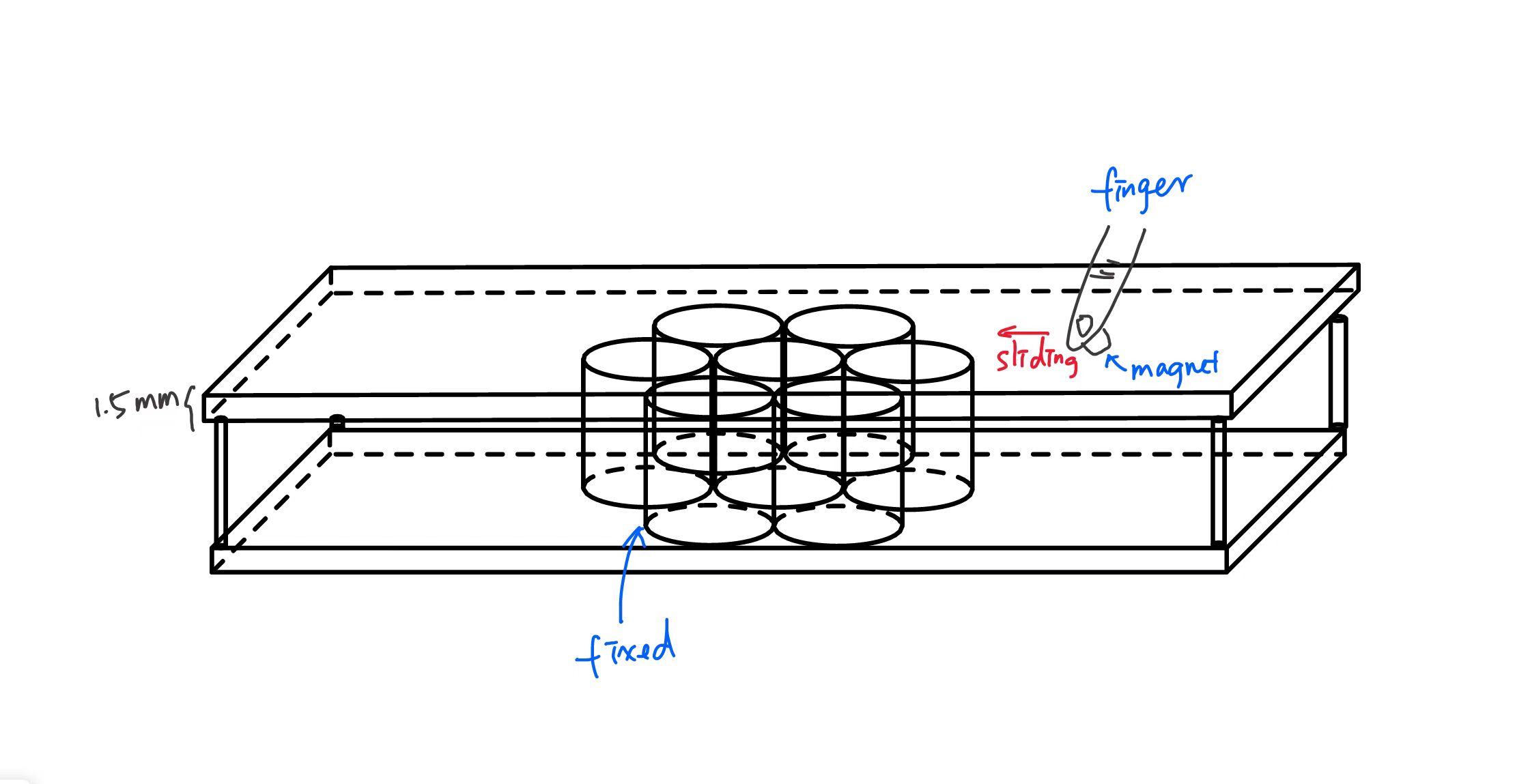
Status: Complete
Goal 3: Mechatronic system prototyping and plan
Description:
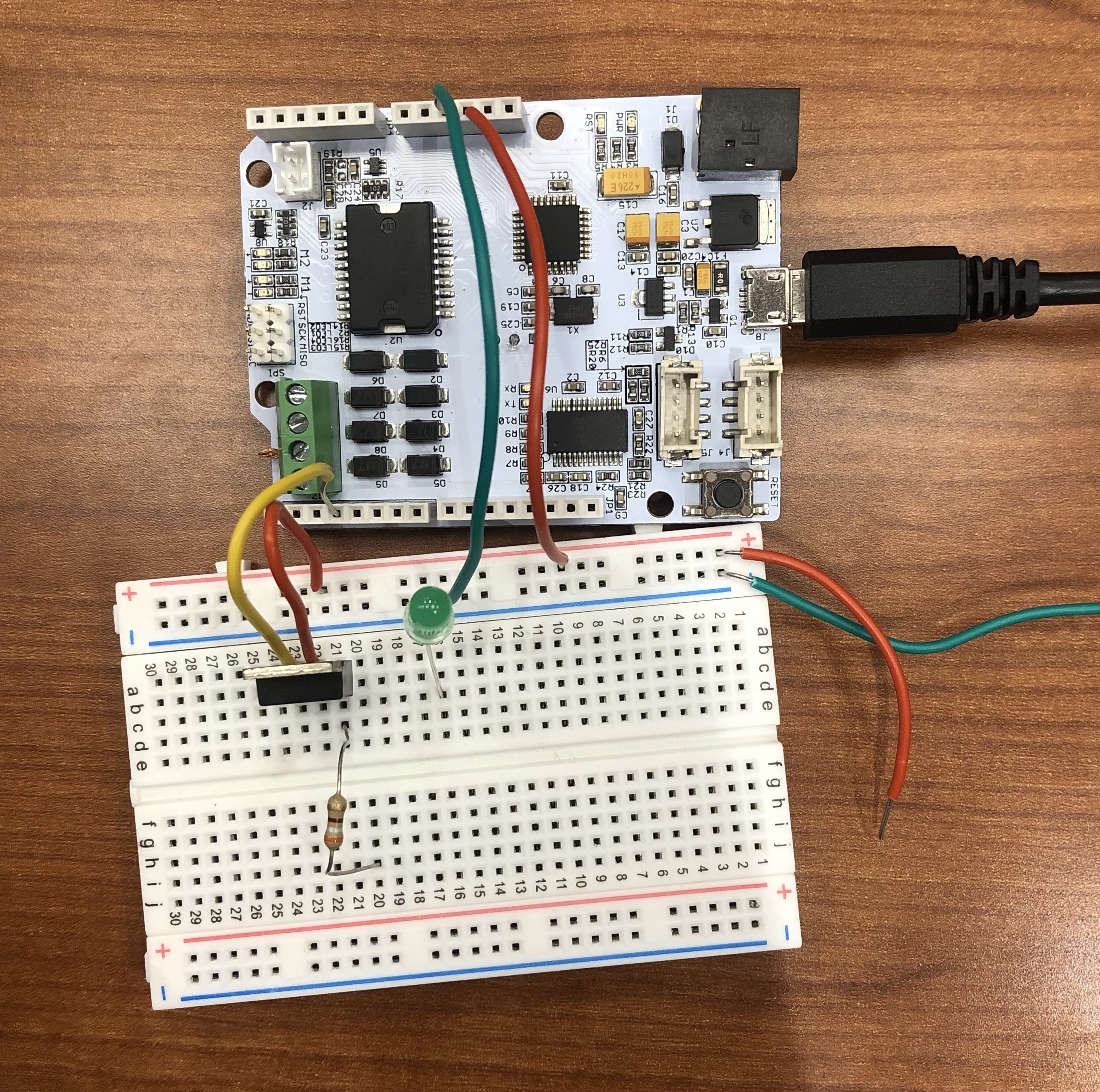
For each coil, it is controlled by a mosfet and Arduino Pin. The Arduino pin provides a PWM signal to turn the coil on and off at 31.25kHz by using the function setPwmFrequency(int pin, int divisor) provided in Homework. By controlling the duty cycle, we can generate different equivalent currents to get different magnetic field strength and forces.
We tested the equivalent currents working well with a LED. With a 50% duty cycle at 31.25kHz, the LED shined with half of the brightness and didn’t twinkle (See picture below).
We also decided that we would display 5 geometries by changing the current within each coil, including a valley, a small bump, a big bump, a horizontal platform, and a slop (Sketch attached below).
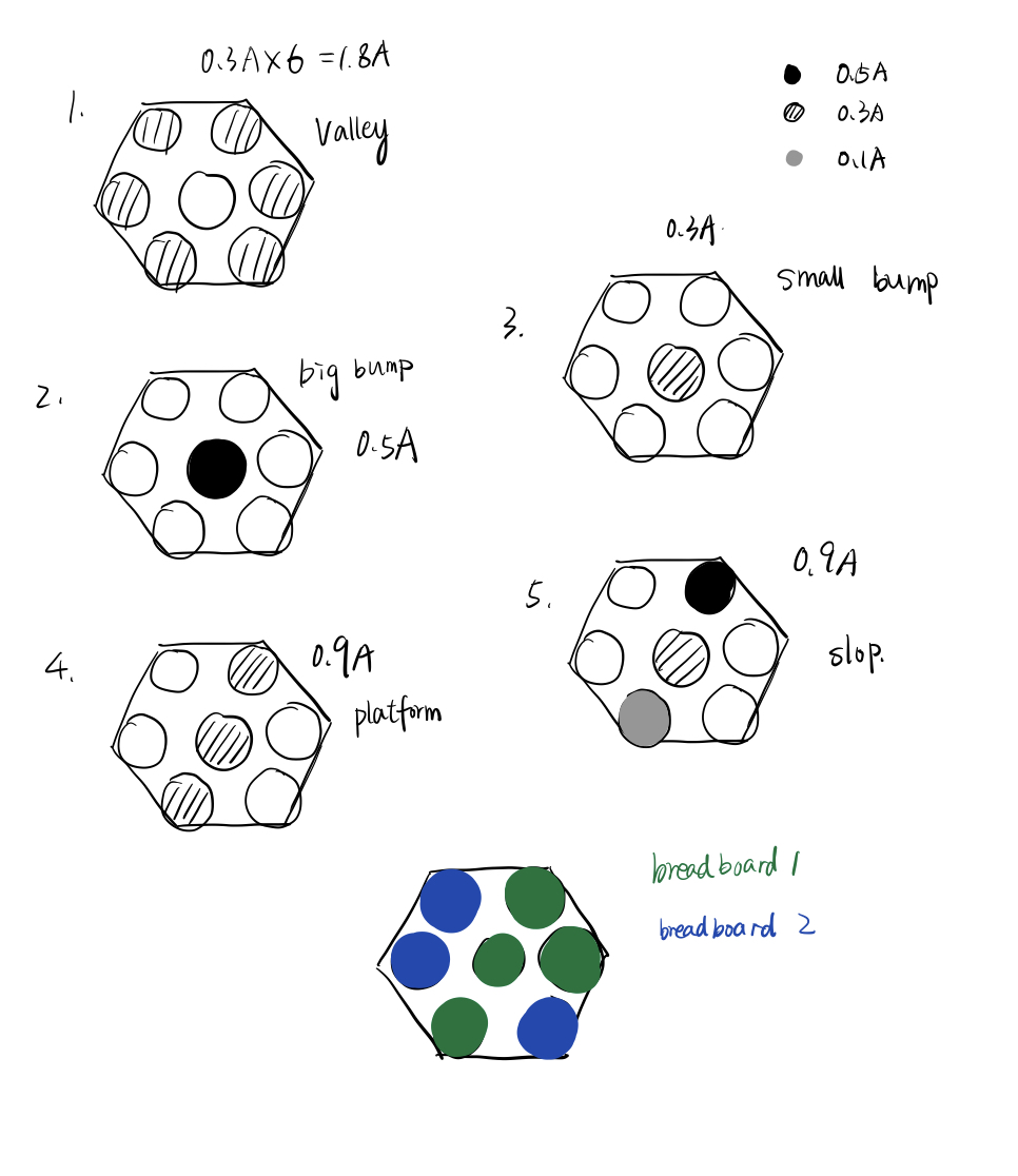
To meet the 1A current limitation of breadboards, we will use two breadboards to distribute the current as the maximum current will be 1.8A.
Status: Complete
Goal 4: Characterize force distribution generated by a single electromagnetic coil
Description:
The experiment is conducted using an Instron testing machine with an electromagnetic coil placed at the bottom stage connecting to a power source and a magnetic fixed at the top stage(Figure below).
The Instron machine is being set in tensile testing mode and zeroed when zero amps of current are applied. The vertical distance between the magnet and the top surface of the electromagnetic coil is fixed at 1.5 mm. Current is gradually increased from 0 A to 0.5 A with an incrementation of 0.1 A and corresponding force data are recorded. Initially, the magnetic and coil are placed with an aligned vertical axis, and the mentioned above testing is repeated as the coil is placed in the position that is 5, 10, 15, 20, and 25 mm horizontal distance from the center axis of the magnet to generated force versus radial distance data(Figure below).
Status: Complete
Checkpoint 2
Goal 1: circuits integration
Description: integrate mosfets and coils to Arduino boards and breadboards to allow Arduino code to control the on/off state of mosfet to decide which coil to activate by allowing current flow through the mosfet. Need to consider the current limitation of the breadboard (1.5 A) and the power supply limitations on voltages (30 V) in order to make our circuits work functionally without melting down.
Status: complete
Goal 2: Arduino programing
Description: Write Arduino code to inform the user of 5 different display modes, valley, big bump, small bump, platform, and slop. After the user input his/her choice, Arduino will turn on different coils with different current. One bug solved is that although 100% PWM corresponds to 0.5A, 60% PWM doesn’t account for 0.3A. Instead we need to increase the PWM to 98% to get 0.36A. With this figured out, our mechatronic system is ready to have more testing and final confirmation.
Status: complete
Goal 3: force mapping based on single coil measurement
Description: In check point 1, we characterized the reaction forces from a single coil to a magnet that is vertically 1.5 mm away from the coil top surface. At a given current of 0.4A, the reaction force is the maximum when the coil and magnet are facing each other, and gradually decreases as the magnet moves away, reaching ~0 N at a distance of 20 mm.

The discrete data points are fitted by a 4-th order polynomial function to get a smooth “Force versus Off-axis distance” function. As the structure is axisymmetric, the obtained 2D function can be extended to a 3D kernel function. For the 7-coil system arranged in a compact way, once the current in each coil is decided, the reaction force on the magnet is the summation from seven coils in total. Based on geometric relations between the magnet to the coils, the force mapping across the 2D plane can be decided.
Status: complete
Goal 4: user test
Description: there are 5 patterns for users to choose. As the user chose pattern 4 to feel a straight bump along the diagonal of the coil array, she successfully recognized the bump without any other perturbation from the inactivated coils. The bump she felt is realistic, noticeable, and stable. The drawback is that as the human hand is moving freely in the air, it is possible to recognize discontinuities of the bump. The reason behind that is the radius of our coil is larger than the radius of the magnet and the force decays rapidly when the position is little away from the center of the coil. As a result, the user gets smaller force when it is slightly offset from the center of the coil. To solve this problem, we will test the performance with a larger magnet to see whether it can help with the problem.
https://youtu.be/DKuI0os_kUY
Status: complete