

Group 8

Our blind spot monitoring system in use.
Helmet-Mounted Haptic Blind Spot Monitoring System for Bicyclists
Project team members: Ian Hong, Hansub Kim, Rekha Ramanathan, and Ethan Tae
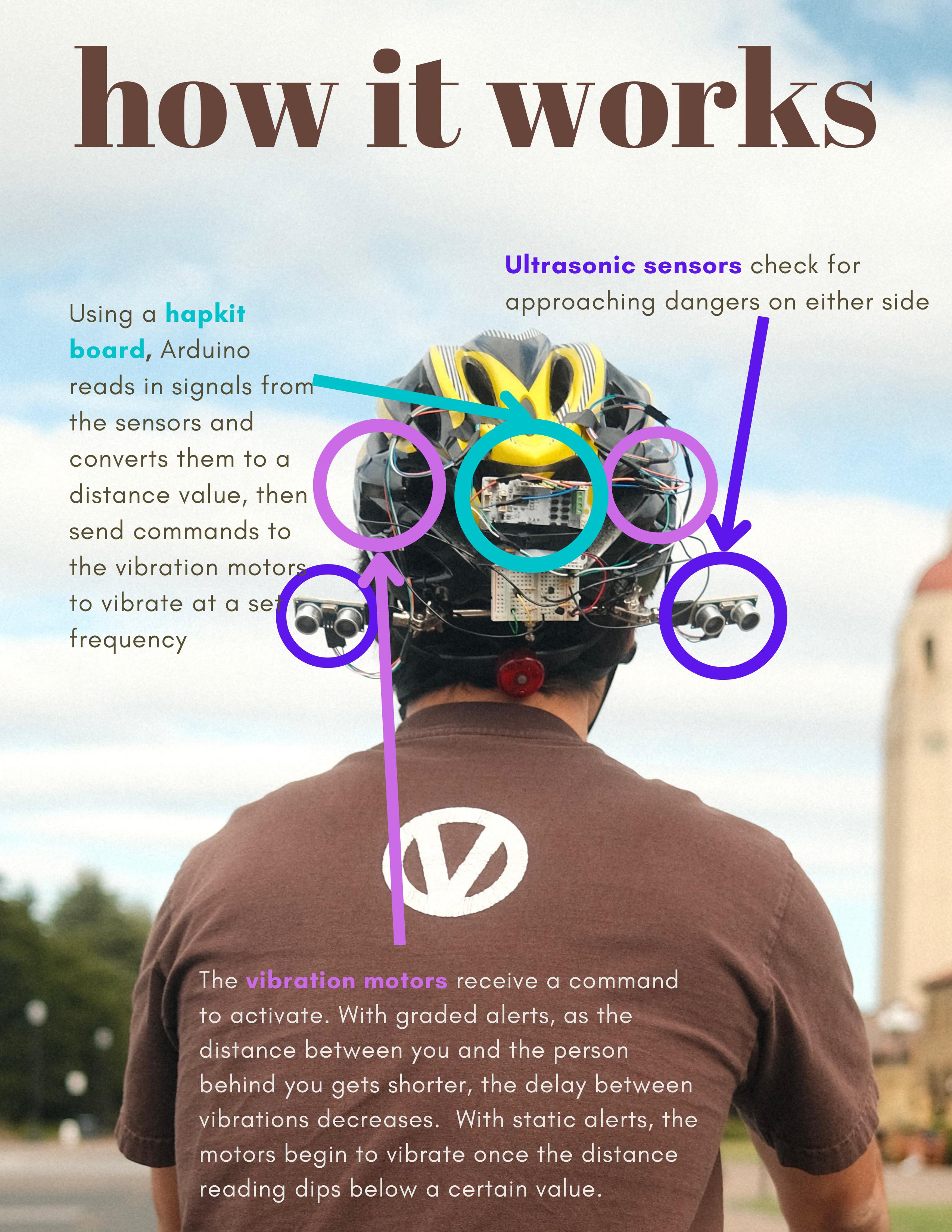
Bicycle commuters constantly face danger from other road users who often act unpredictably and maneuver very closely. To solve this issue, we designed a helmet for bicyclists with built-in blind spot monitoring. Using ultrasonic distance sensors, the helmet constantly tracks approaching hazards in the user’s blind spots that are up to 1.5m away. When the hazards get too close, it triggers haptic vibration motors located on either side of the helmet to alert the user to the danger. We developed a fully-functional prototype, and tested it during demo day to see what haptic signal type users preferred. 88% of participants we tested preferred having a vibration signal that increased in frequency as objects drew closer.
On this page... (hide)
Introduction
Blind spot monitoring is a common technology in modern cars that uses radar to detect nearby cars. By providing visual, audible, and/or haptic feedback, the car alerts drivers to motorists in their blind spot to make lane changing easy and safe.
Just like driving, biking can be a dangerous activity if other road users are not careful. On college campuses, other bikers and electric scooter or skateboard users tend to behave recklessly. During ‘rush hour’, it’s not uncommon to be passed at high speeds by impatient students, who squeeze through the narrowest gaps possible. When biking, this means that it can be very dangerous to deviate from a straight path to make turns. Furthermore, biking on roads means being in close proximity to cars, which can silently and quickly creep up and pose a hazard.
While blind spot monitoring is increasingly common on even base level cars, it is not yet widely found on smaller vehicles like motorcycles and bicycles. There are a small number of motorcycle blind spot monitors available, but little to no bicycle-mounted systems. To address these dangers and fill this niche, we created a helmet-mounted haptic blind spot monitoring system. The solution we developed uses two ultrasonic sensors to detect bikes or vehicles in the user’s blind spot and interprets the distance data to drive vibration motors within the helmet to alert the user. Our use of haptics allows users to quickly identify approaching dangers without taking their eyes off the road, making bike commutes much more stress-free.
Background
Haptic feedback is often used alongside audio cues in modern cars to alert drivers of potential dangers related to lane changes, blind spots, and sharp curves (Tao et al. 2021). This has led to the creation of a decently-sized body of literature concerning the types of haptic vibrations that are the most useful.
Studies show that vibration perception can be magnified when it occurs on top of bone, so placing the motors close to the skull would be ideal for our implementation (Gilman 2002). Previous work also supports the ‘Simon effect’ where participants react more quickly to direction-based stimuli if they are correctly spatially located (Lu et al. 1995). This suggests that placing the motors far apart on the left and right sides of user’s heads is key to providing them with actionable warning data.
Comparisons of different haptic signals show that cutaneous feedback is the easiest to notice and most comfortable, confirming our signaling system selection (Tao et al. 2021). Studies indicate that pulse length is one of the key factors in delivering a noticeable vibration signal that is not annoying, with the optimal range falling between 50 and 200ms (Kaaresoja et al. 2005). Furthermore, research suggests that users prefer graded haptic and auditory warnings (i.e. scaling with danger level) over static threshold ones (Lee et al. 2004).
While haptic feedback is common in cars, some companies have expanded beyond this to also create wearable haptic warning systems. Arc Vector’s haptic motorcycle jacket aims to warn riders of potential collisions. Motors in the shoulders of the jacket will buzz to indicate the presence and direction of a potentially dangerous approaching vehicle (Hinchcliffe 2018).
Methods
Our detailed parts list in the Files section outlines all components used in this project. A high-level diagram of the system is shown below.

The first main part is the sensor array, which detects bikes or other vehicles in the user’s blind spots. We used two (2) Arduino HC-SR04 ultrasonic distance sensors, which have a detection angle of around 30 degrees and a claimed range of up to 4 meters (Cytron Technologies 2013). By mounting them on the back of the helmet and angling them off to either side, we get both directional and distance information for approaching hazards.
The second is the processing unit to output haptic signals depending on the readings from the ultrasonic sensors. We ran our solution on one (1) HapKit board, which is based on an Arduino model. This unit takes input voltages from the distance sensors, runs code we developed to convert those voltages into distances, and then drives the vibration motors accordingly.
The third and final piece of hardware is the vibration motors. We used two (2) Jameco 2234353 eccentric rotating mass (ERM) motors. Guided by existing literature, we experimented with the placement and vibration signals of these motors to optimize the conveyed signal.
Electronics Design
A diagram of our fully integrated circuit is shown below. We used male-male jumper cables to make the majority of these connections, and tinned the wires’ tips for the others.

The HapKit board controls the device, but because of hardware limitations, we do not directly drive current through the digital pins. Instead, we connect the board’s 5V and GND pins to the power rails on an external half breadboard. The vibration motors connect directly to the 5V rail through one lead, and are routed through a pMOS transistor to ground. The gates of these transistors are connected via 1kOhm resistors to digital pins on the HapKit board. For our ultrasonic sensors, we connect their VCC and GND pins to the corresponding rails. We route their ECHO and TRIG pins directly to digital pins on the HapKit board.
Hardware Integration
Our fully assembled prototype hardware is shown below.

To mount the hardware together and to the helmet, we used less-permanent methods to expedite our assembly process and keep cleanup and costs to a minimum.
We attached the motors to the helmet using electrical tape in the locations shown in green in the image below. We placed the motors close to the skull, right underneath the helmet’s padding right behind the user’s temples (Gilman 2002). To maximize users’ directional discernment, we also located the motors as far away from each other as possible (Lu et al. 1995). Because of their small size, the motors are not noticeable during normal use.

To keep our electronics package small, we attached the HapKit board on top of the breadboard using electrical tape wrapped around unused areas. After applying adhesive pads around a flat area on the backside of the helmet, we attached the electronics. For additional security, we added a zip tie around the assembly. The photo below shows the electronics package at an intermediate mounting stage with a temporary cable tie.

To maximize our ultrasonic sensors’ useful detection cones, we pointed them slightly off to either side of the helmet’s rear (Cytron Technologies 2013). This ignores less-dangerous hazards directly behind the user, allowing the full 30 degree field of view to sweep the user’s sides. Because the helmet has many complex geometries, mounting the sensors directly onto the helmet was not an option. To hold our ultrasonic sensors at the right angles, we used the spanning bar of a soldering Helping Hand, boxed below in red.

Using cable ties and hot glue, we attached the bar to the rear of the helmet and controlled its displacement and rotation in all degrees of freedom. We adhered popsicle stick segments to the backsides of our ultrasonic sensors, then securely clamped the sticks into the spanner. With a protractor and level, we carefully oriented the sensors in the right directions and secured them within the setup. We oriented the sensors as close to 15 degrees off to either side as possible to maximize the usable vision cone, but the alignment was inexact. Additional photos of the completed device are shown below.


Dynamic System Control
Our commented code can be found in the Files section.
After reading the ultrasonic sensor data, the program collects current hazard flags from each side based on our distance danger thresholds. Then, it runs the motors in sequence for set pulse lengths and stores pulse gap reset times for each. As discussed previously, the pulse gap is our dynamics study and is either static or linearly scaling. We conducted a user study within our group to determine optimal pulse length and gap selections. For the static signal, we chose to use a stable 200ms separation to avoid overwhelming users, while still being urgent. The graded signal linearly ranges from a 300ms gap at our functional maximum range of 150cm to 50ms at the lower bound of 25cm.
The code we created uses a blend of delay() calls and millis() timekeeping. We used delay() to actuate the motors for set amounts of time in sequence, and rely on millis() for pulse gap spacing. This allows us to ensure that the motors are properly offset from each other when hazards are detected on both sides, allowing directional discernment. We wanted to use millis() for more accurate timekeeping of both pulse lengths and gaps, but the loop runs too slowly with that implementation. Using delay() for both would potentially slow down the loop to 800ms per instance, which would be undesirable.
We also investigated implementing a low-pass filter to clean up our data. However, we did not end up using this because our slow loop makes it unnecessary. Our code for this filter can be found in the Files section. It takes in a cutoff frequency, sample frequency, and a boolean value to set whether the sample frequency can be changed. From triangular traversal distance approximations, we estimated that we would want our cutoff frequency to be around 5Hz.
Results
Overall, we were pleased with how our prototype device performed. While the sensors’ range was limited, they were mostly reliable up to ~1.5m. Within that range, we were able to accomplish our project’s goals and rapidly deliver haptic blind spot warnings. We cover the limitations of the device and possible next steps in the Future Work section.
Our dynamics study tested whether participants preferred static signals or graded signals. Existing literature suggests that people prefer graded haptic warnings in cars, and we wanted to verify that for our helmet adaptation (Lee et al. 2004). We received data from 13 participants during the open house; including our group’s responses, we had a total of 17 data points. Of these 17, 15 preferred graded signals and 2 preferred static signals. These values correspond to 88% and 12% of participants respectively. The data is represented in the graph shown below.

Qualitatively, users who preferred graded signals generally liked the additional distance information that it provided. Interestingly, some mentioned that the graded signals made differentiation between right side and left side vibrations more clear. Among participants who preferred the static signal, all mentioned that paying attention to the graded signal required too much brain power to distinguish how far a hazard was. In a busy, high-stress biking environment, this could be dangerous and distracting. A photo of Professor Okamura testing our device is shown below.

Future Work
As we have only developed and tested an early-stage prototype, future work could make the system more robust. Currently, the HapKit board is either tethered to a laptop or powered with a portable charger. For system implementation on a bike, the power source could be mounted to the helmet, allowing the assembly to be portable. Related to this, we would need to conduct a power draw study to determine the necessary battery specifications.
Improving hardware mounting methods could make the system more reliable. Currently, the sensor mounting uses temporary and easy-to-disassemble methods including adhesives, popsicle sticks, and zipties. In future iterations, customized 3D-printed parts could increase the structural integrity of the helmet. The system should also undergo thorough crash testing to ensure it does not compromise the user’s safety.
Upgrading the system’s hardware and/or software could improve its performance. We used very low-cost ultrasonic sensors that were okay for prototyping purposes but were limited in some ways. Their range was short, they experienced a lot of noise, and their cone of vision was restricted. Additionally, we ran into difficulties with processing the data on the low-bandwidth Arduino board. We had to increase the loop time using blocking delays because the minimum loop time was too long to allow non-blocking timekeeping. Using a faster processor, multiple devices, or threading the program could significantly improve system responsiveness.
We found that the usefulness of the haptic signals was greatly affected by the contact points of the vibration motors on the helmet. When various participants wore the helmet, the difference in fit on their head affected how well they could feel the left- and right-side vibrations. In future iterations, we could run a larger-scale study to confirm where to place the vibration motors to ensure best contact with the head. Some participants noted that they could hear the motors quite strongly, suggesting that bone conduction could be a viable method of conveying warnings.
User testing could help to refine the prototype. New dynamic studies could test whether users might prefer haptic signals through their handlebars instead of on their head. This might make the system more appealing to young adults, who tend to not like wearing helmets. Additionally, we could test the system with users in different traffic and weather/lighting conditions, and investigate weatherproofing the setup for harsher climates.
Files
Commented code: Attach:Team8_code.zip
Parts list with prices: Attach:Team8_Parts.xlsx
Additional product promotional materials:


References
Cytron Technologies. “Product User’s Manual – HCSR04 Ultrasonic Sensor.” May 2013. https://web.eece.maine.edu/~zhu/book/lab/HC-SR04%20User%20Manual.pdf.
Gilman, Stephen E. “Joint Position Sense and Vibration Sense: Anatomical Organisation and Assessment.” Journal of Neurology, Neurosurgery & Psychiatry 73, no. 5 (2002): 473–77. https://doi.org/10.1136/jnnp.73.5.473.
Hinchliffe, Mark. “Haptic Jacket Warns Rider of Collision.” Motorbike Writer, November 12, 2018. https://motorbikewriter.com/haptic-jacket-warns-collision/.
Kaaresoja, Topi, and Jukka Linjama. “Perception of Short Tactile Pulses Generated by a Vibration Motor in a Mobile Phone.” First Joint Eurohaptics Conference and Symposium on Haptic Interfaces for Virtual Environment and Teleoperator Systems, n.d. https://doi.org/10.1109/whc.2005.103.
Lee, John D., Joshua D. Hoffman, and Elizabeth Hayes. “Collision Warning Design to Mitigate Driver Distraction.” Proceedings of the 2004 conference on Human factors in computing systems - CHI '04, 2004. https://doi.org/10.1145/985692.985701.
Lu, Chen-hui, and Robert W. Proctor. “The Influence of Irrelevant Location Information on Performance: A Review of the Simon and Spatial Stroop Effects.” Psychonomic Bulletin & Review 2, no. 2 (1995): 174–207. https://doi.org/10.3758/bf03210959.
MakerPortal. “HC-SR04 Ultrasonic Distance Sensor.” May 27, 2022. https://makersportal.com/shop/hc-sr04-ultrasonic-distance-sensor.
Tao, Jini, Duannaiyu Wang, and Enyi Zhu. “Evaluation of Haptic Feedback Cues on Steering Wheel Based on Blind Spot Obstacle Avoidance.” Cross-Cultural Design. Applications in Cultural Heritage, Tourism, Autonomous Vehicles, and Intelligent Agents, 2021, 253–66. https://doi.org/10.1007/978-3-030-77080-8_21.
Appendix: Project Checkpoints
Checkpoint 1
We did not include detailed checkpoint goals in our initial project proposal, so our targets have been a little more freeform. Because we anticipated that our hardware assembly and testing would be straightforward, we prioritized obtaining the required materials and planning out our design and experimentation steps.
As we moved forward from the proposal to creating our design, we updated some of our solution’s details. After seeing the geometry of our helmet, we decided to create mounting brackets for the ultrasonic sensors. This will help us ensure baseline alignment and potentially allow us to adjust them to a small degree during testing. We also plan to mount the HapKit board on the helmet to keep the inter-component wires short. Because all the components are light, we do not anticipate any ergonomic issues.
Our updated materials list is shown below:
- (1) bike helmet
- (1) HapKit board
- (1) microUSB cable
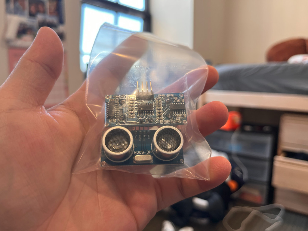
- (2) Arduino HC-SR04 ultrasonic distance sensors
- (2) Jameco 2234353 eccentric rotating mass (ERM) motors
- (bundle) breadboard jumpers
- (bundle) alligator clips
Of these parts, the HapKit board, microUSB cable, and ERM motors were provided in the course kits. We purchased and have received the HC-SR04 ultrasonic sensors, as seen in the photo below:
From our team members’ belongings, we were able to obtain a bike helmet, breadboard jumpers, and alligator clips. These items can be seen below:

Having gathered the requisite hardware and fleshed out some of our project’s nuances, our current development roadmap is roughly as follows:
Immediate Next Steps
- Conduct dynamic systems study with vibration motors to identify ideal location, intensity, and type of stimulus applied to the user during simulated warning scenario
- Determine ideal mounting angles, locations, and sensing range for ultrasonic sensors on helmet
- Filter ultrasonic sensor output to only useful data
- Write algorithm to apply varying haptic stimulus based on distance readings
Follow-up Steps
- 3D print motor, sensor, and Arduino mounting brackets, or use tape/hot glue if development and manufacturing timeline is too long
- Test fully-functional prototype in dynamic biking environment
We plan to have all immediate next steps completed by Checkpoint 2 (5/27). If we do not have time to complete the follow-up steps by Checkpoint 2, we will use the period between Checkpoint 2 and demo day to finalize the hardware and gather our test data.
Checkpoint 2
In the week starting 5/23/22, we had three build days, over the course of which we conducted a dynamic systems study as well as soldered, calibrated, and debugged our setup. We also sequentially developed and tested a working prototype of our distance-based haptic feedback algorithm.
Our work focused on a few key areas: evaluating existing literature, electronics and sensor implementation, digital filtering, dynamics studies, and system integration.
Evaluating existing literature:
We dug into existing literature on vibration sensitivity as well as precedents for haptic notification signal types.
Studies show that vibration perception can be magnified when it occurs on top of bone, so placing the motors close to the skull would be ideal for our implementation (Gilman 2002). Previous work also supports the ‘Simon effect’ where participants react more quickly to direction-based stimuli if they are correctly spatially located (Lu et al. 1995). This suggests that placing the motors far apart on the left and right sides of user’s heads is key to providing them with actionable warning data.
Comparisons of different haptic signals show that cutaneous feedback is the easiest to notice and most comfortable, confirming our signaling system selection (Tao et al. 2021). Studies indicate that pulse length is one of the key factors in delivering a noticeable vibration signal that is not annoying, with the optimal range falling between 50 and 200ms (Kaaresoja et al. 2005). Furthermore, research suggests that users prefer graded haptic and auditory warnings (i.e. scaling with danger level) over static threshold ones (Lee et al. 2004).
Motor Implementation:
We initially ran the vibration motors by connecting one lead to ground and one to a digital pin that would be written to 5V. However, the limited current through these pins caused the motor vibrations to be far too weak. To fix this, we directly connected the motors to the higher-current 5V voltage supply pin and controlled the motors’ actuations with pMOS transistors. Our functional breadboard setup for this is shown below:

Because both motors draw current from the same pin, we realized we might run into issues if both are active at the same time. To avoid this, we decided to programmatically have the motors activate in sequence and never together. We also think this will be beneficial for users, who might be confused if the whole helmet starts vibrating.
The other motor parameters (pulse length, pulse gap, and location) are discussed further in the dynamics study section.
Sensor Implementation:
As with the motors, we ran into the issue that the two ultrasonic sensors could not be run at the same time, and had to be run one after the other. This occurs because the sensors are at risk of mixing signals if they are activated together. We chose to have the ultrasonic sensors also run in sequence within our loop.
While we initially planned to develop 3D-printed mounts for our ultrasonic sensors, we decided against it. Firstly, we realized it would be very difficult to develop CAD models of our bike helmet’s many curves. We would end up roughly mounting a manufactured object to the curves anyway, so we chose to skip the custom mounts and instead directly attach the sensors to the helmet using temporary adhesives. We have identified flat locations on the helmet that we can use for this, and will use intermediate materials to ensure the proper angular offset.
Digital Filtering:
We wanted to isolate useful distance signals and ignore potential noise (e.g. falling leaves, stationary objects, RMS noise, etc.). To do this, we implemented a digital low-pass filter in Arduino using reference materials produced by CurioRes on YouTube and GitHub.
We selected our baseline cutoff frequency by examining our ultrasonic sensor’s vision cone at varying distances. From the specification sheet and provided performance test shown below, the sensor has an effective angle spread of 15 degrees either side of center (Cytron Technologies).

The document also specifies that the sensor has a distance sensing range of 2cm to 400cm. We found that in practice, the sensor was not able to reliably detect objects beyond 200cm. Using a triangular approximation of the vision cone, we find that the lateral width the sensor can measure at a distance of 2 meters is approximately 2*2m*sin(15deg) = 1.04m. We combine this with a baseline biking speed of 4.5m/s, meaning that a stationary object would traverse the vision cone’s width in 1.04m / 4.5m/s = 0.23s. This roughly suggests the period of its signal, which we can invert to find its frequency as 1/T = f = 4.35Hz. Including an additional factor of safety, we settled on a cutoff frequency of 5Hz. Our low-pass filter code accounts for the provided 40Hz sampling rate of the ultrasonic sensor (MakerPortal).
Dynamics Study and Testing:
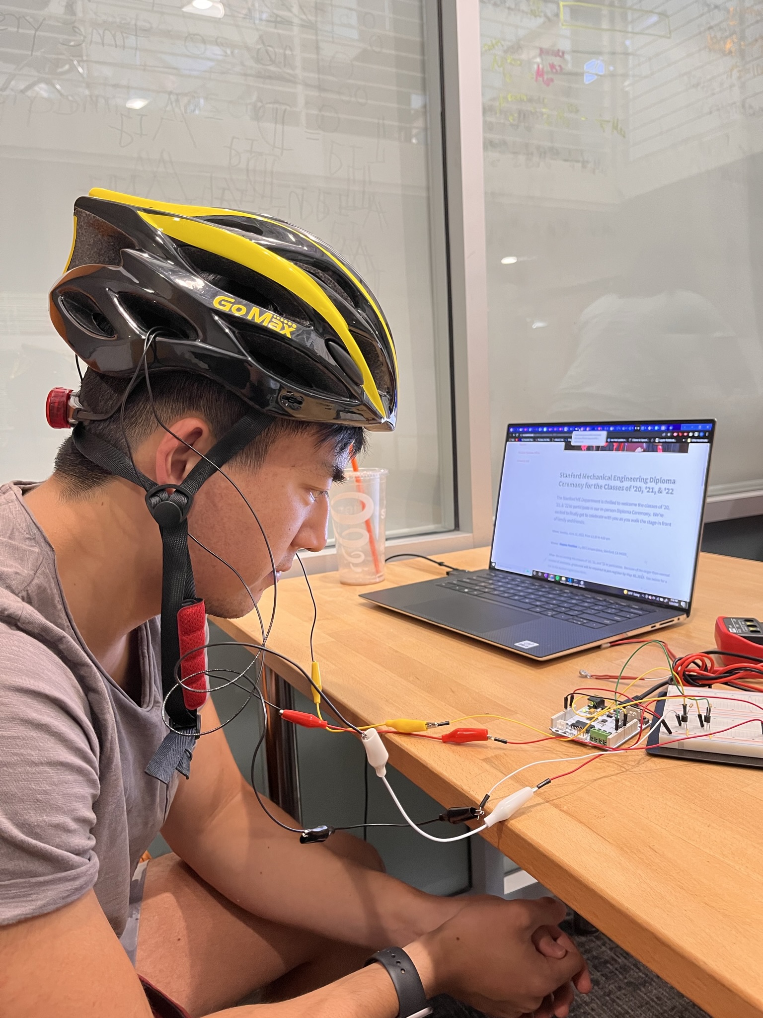
Because of our limited working time, we conducted research and used a small-scale study on each of our four group members to determine the ideal vibration pulse location, length, and separation/type. We plan to continue aspects of our study on demo day. A photo of our study in progress is shown below:
The first related parameter we selected was motor location in/around the helmet. Following what we found in our literature research, we wanted to place the motors close to the skull (Gilman 2002). This meant finding locations as far on the inside of the helmet as we could get without disturbing ergonomics. We also wanted to locate the motors as far away from each other as possible to maximize direction discernment (Lu et al. 1995). Combining these two criteria, we selected the locations shown in green in the image below:
At these locations, the motors rest right underneath the helmet’s padding right behind the user’s temples, putting them in very close proximity to the user’s head. Because of their small size, they are not noticeable during normal use. We believe the motors do not pose a safety hazard during crashes thanks to their size. The next parameter was pulse length, which we selected through our localized study. Guided by the research done by Kaaresoja et al., we all experienced alternating left- and right-side pulses from 50ms to 250ms in 25ms increments. Two of our members preferred 150ms pulses, while the others favored the 250ms pulses. We settled on an average of 200ms to strike a balance between being noticeable and not being annoying.
Finally, we wanted to use pulse separation to convey hazard warnings to our users. The two choices we settled on were static signals (unchanging pulse gap) and graded signals (decreasing pulse gap with increasing danger level). Previous research suggests users prefer graded signals, but we want to reevaluate this in context of our shorter-range and higher-frequency bike alert system (Lee et al. 2004). While we did not have time to conduct this study within our group before Checkpoint 2, we will have users compare and rate the two alert types during demo day. For both alerts, we wanted to determine what duration or range of pulse separation was useful without being overly obtrusive. All of our members tried pulse gaps from 25ms to 250ms with a 200ms pulse length, and all agreed that a range of 50ms to 300ms was ideal. For the static signal, we opted to go with a stable 200ms separation to avoid overwhelming users, while still being urgent. The graded signal linearly ranges from a 300ms gap at our functional maximum range of 200cm (might need to be lowered to 150cm depending on test environment) to 50ms at the lower bound of 25cm.
Full System Integration:
After we had developed our frameworks for using the distance sensors and vibration motors, we began to combine the two into a functional system. Our current test bed is shown below:

There were a number of considerations we made that we had to work into our integrated Arduino code. The first is blocking – during the vibration motor calibration segment, we used delay() calls to set the pulse length and gap times. However, using that sort of implementation in practice would mean a delay of up to 800ms per loop if both motors were activated. To work around this, we settled on a blend of delay() calls and millis() timekeeping. We used delay() to actuate the motors for set amounts of time in sequence, and rely on millis() for pulse gap spacing. This allows us to ensure that the motors are properly offset from each other when hazards are detected on both sides, allowing directional discernment. We wanted to use millis() for more accurate timekeeping of both pulse lengths and gaps, but the loop runs too slowly with that implementation.
We created a functional integrated sensor/motor processing program. After reading the ultrasonic sensor data, the program collects current hazard flags from each side based on our distance danger thresholds. Then, it runs the motors in sequence and stores pulse gap reset times for each. As discussed previously, the pulse gap is our dynamics study and is either static or linearly scaling.
Next Steps:
In the remaining few days before demo day, we will work on fully mounting all hardware to our helmet to minimize tethering. We will also test and optimize our algorithm’s first-pass graded signal, modifying the pulse parameters to get to what we subjectively feel is the best scaling.