

Derin Michael
Haptic Battle Pong
On this page... (hide)
By Derin Dutz and Michael Raitor

Visuo-haptic augmented reality: the final frontier. These are the voyages of the Haptic Battle Pong project. Its two-week mission: to explore strange new virtual worlds, to seek out new haptic effects and new user experiences, to boldly push the boundaries of what we see and what we feel. (You will only truly appreciate this paragraph if you carefully listen to the music in the game)
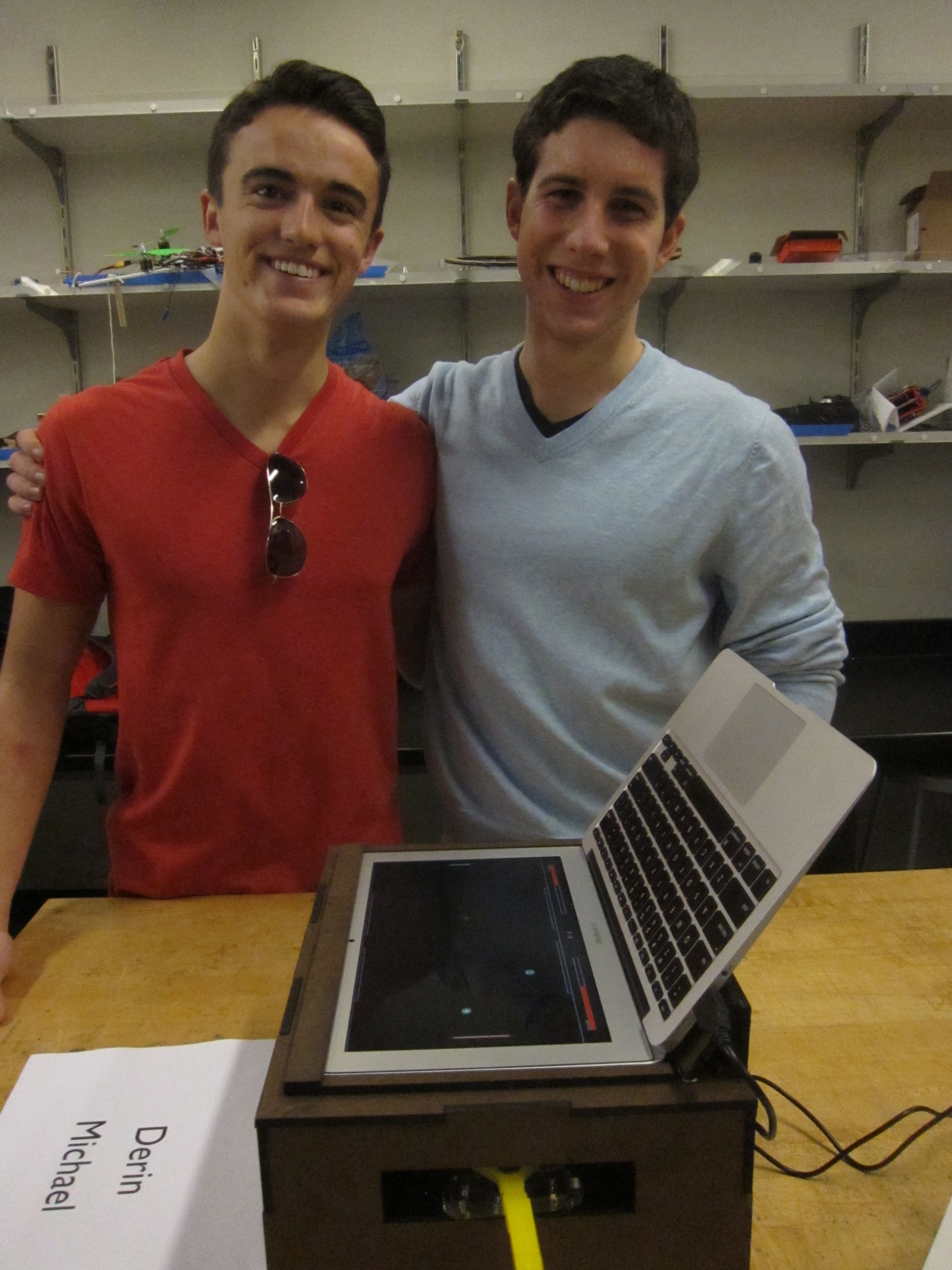
Our project at the Stanford Haptics Open House
Introduction
The human condition is multi-modal: our senses of touch and vision are not isolated, but rather operate in close harmony. The goal of this project was to explore visuo-haptic augmented reality by improving a user's ability to connect with a virtual world. Through the use of visuo-haptic feedback, we sought to improve intuitional navigation and user response in a virtual environment. To this end, we created the Haptic Battle Pong game. The game is based off the impact of a paddle hitting a bouncing ball. Rather than being a disconnected onlooker watching events occur on a screen, the user feels as well as sees virtual events in the game. Haptic feedback allows the user to feel the ball hit the paddle as well as to feel the various haptic-effect-driven power-ups.
Background
Our inspiration for the concept of the game came from a game Derin played as a child with his brother (http://www.ponggame.org/battle-pong.php). We realized a similar game would be a perfect environment to investigate the merits of visuo-haptic augmented reality. The software that was written for this project utilizes foundational Arduino code that Tania Morimoto wrote for the original Hapkit (http://hapkit.stanford.edu/build.html). The rest of the Arduino code that is used is completely original, as is all of the Processing code. Halfway through our project, we learned about a similar project to ours made the previous year by graduate students in the CHARM lab, (http://charm.stanford.edu/ME327/JeffAndCurtis). We reference their project here to showcase similar work in the field, not because we derived any inspiration from their project. We explicitly did not look at their website in order not to have our ideas warped, and our design is in no way based on theirs.
Design
Software
Summary
The software for the project is divided into two parts: a back end programmed in Arduino which is responsible for relaying information between the various motors and sensors and the computer and a front end user interface which is programmed in Processing.
Back End
Arduino Code: Main Board
Outline
The main board does all the information processing and relays information between the two motors and the two magnetoresistive sensors and the computer.
General Design
The program first starts the serial port so that the board can communicate with the computer. The program then sets up the various input and output pins so that the board can send information to the two motors and receive information from two sensor position pins (one for the first motor, and one for the second). The sensors are magnetoresistive sensors that were used because they work quite well and are inexpensive. The program then keeps track of the values of the magnetoresistive sensor readings and the number of flips the motors make. If the motors flip over 180 degrees, the program adjusts the variables accordingly to take that into account. The program also sets pulse-width modulation frequencies for the motor output pins so that the motors can receive varying output signals. The program then keeps parameter names for the various parts of the paddles and computes the angle of the sector by using the positions of the magnetoresistive sensors. Then, the x positions and velocities of the handles are computed. The program sends the x positions of the handles via the serial port to the computer.
The program then reads from the serial port. Depending on the commands the computer sends, the program can reset the software on the Arduino, output given forces to the motors, or initiate power up loops. The program then checks which power up loops are active. If the dampening effect is active, the program outputs a force that provides the dampening effect to the desired motor by applying a force related to the velocity of the user's paddle. If the random force effect is active, the program uses a counter to output a force that provides a seemingly random effect to the desired motor.
The program then determines the correct direction for the motors and computes the duty cycle. The computer makes sure the duty cycle is set between various parameters so that the motors can't be harmed. Finally, the program converts the duty cycle to an output signal and outputs the signal to the respective motors.
Specific Design
See the commented BattlePongArduino.ino file to walk through each step of the program and see what each step does.
Arduino Code: Secondary Board
The secondary board must be told to do nothing. All the information processing is done on the main board.
Front End
Processing Code: Computer
Outline
The Processing code implements the Haptic Battle Pong game and displays the graphical user interface on the screen.
General Design
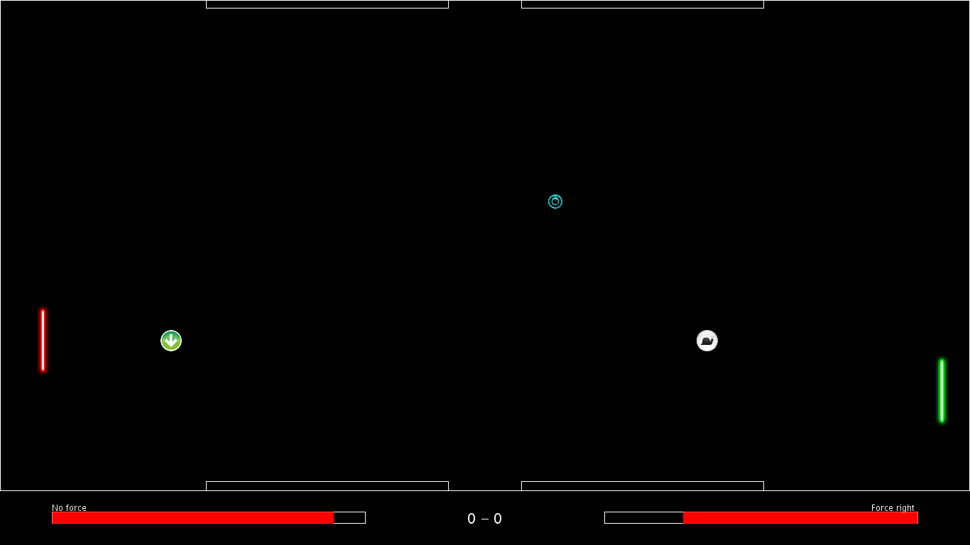
The program sets up the serial port, various sounds, the size of the screen, and various variables and images. The program then goes through the main drawing loop. The program displays a black background, and draws the game rectangle and player information on top of it. The player information consists of life bars for each player, text displaying the forces the players are currently feeling and text displaying the score. The program then checks whether the game is over. The game ends when either player wins more than three turns, and a turn is over when a user loses all of their life. If the game is over, the program sets the forces on the paddles to 0 and produces an appropriate display.
If the game is not over, the program draws the current game state. The program draws four power-up bricks on the screen that the players can hit to generate power ups. The program also draws the paddles for each player on the screen. The program then checks whether either paddle has the autopilot activated. If the autopilot feature is on, the computer will play the game for that player and move the paddle virtually and physically to follow the ball. The program then checks for collisions. If the ball hits any of the four walls of the game, either of the player paddles, or either of the power up bricks, the ball bounces accordingly. If the players miss the ball, they lose life. If the ball hits a power-up brick, the current player launches a power-up from their paddle at the opponent. If a power-up hits a player, that player loses life and feels the effect of that power-up. The four power-ups are a force that pushes the player's paddle upwards, a force that pushes the player's paddle downwards, a force that causes a dampening effect on the player's paddle, and a random force that seemingly randomly moves the player's paddle up and down. If a player successfully hits their opponent with one of their power-ups, any force they would be feeling is eliminated. If the power-ups hit any of the walls, the power-ups disappear. The program then updates the ball. Depending on what the ball hits, the x and y velocities of the ball are updated and the ball moves accordingly. Finally, the program moves the power-ups on the screen.
If the autopilot feature is on for a player, that player's paddle moves to follow the ball. The autopilot feature for player 1 causes the player's paddle to follow the ball by applying a strong force in the direction of the ball and then setting the force to 0. Thus, the paddle moves in a jittery manner. This autopilot implementation is very consistent and never misses the ball, but is a little bit slower than the implementation for player 2. The autopilot feature for player 2 causes the player's paddle to follow the ball by constantly applying a relatively weaker force in the direction of the ball. Thus, the paddle moves in a smooth manner. This autopilot implementation is less consistent but faster than the implementation for player 1.
The program also allows the user to enter keyboard strokes. If the user presses the �r' key, the Arduino software is reset. This is used if there are any hardware or software lags or issues. If �f' is pressed, the forces are reset to 0. This is used if there are hardware issues regarding the motors. If �y' is pressed, the autopilot for player 1 is toggled, and if �w' is pressed, the autopilot for player 2 is toggled.
When the program is told to apply a force given the player to apply the force to and the direction in which to apply the force, the program uses a custom protocol to send information via the serial port to the board. The board then reads this information and applies the corresponding force or power-up effect. When the program receives an event from the serial port, the program reads the handle position data and adjusts the paddle positions on the screen accordingly. When the program is stopped, the program makes sure to close all the sounds.
Showcasing player 1 autopilot
Specific Design
See the commented BattlePongProcessing.pde file to walk through each step of the program and see what each step does.
Making The App
To make Haptic Battle Pong a standalone application, use the convenient function provided by Processing. Open a picture in your favorite photo editing software. Add the "Haptic Battle Pong" text to the image, round the corners, and convert it to a png file. Then, convert it to an icns file and use it as the icon for the Haptic Battle Pong application.
Showcasing the standalone application and player 2 autopilot
Building The Project
- Put the BattlePongArduino.ino code on the main board.
- Put an Arduino file that does nothing on the secondary board.
- Run the BattlePongProcessing.pde script in the Processing program.
- Create a standalone application from the Processing program.
Electronics
Summary
The electronic design for Haptic Battle Pong consists of getting the two boards to communicate with each other and with the computer.

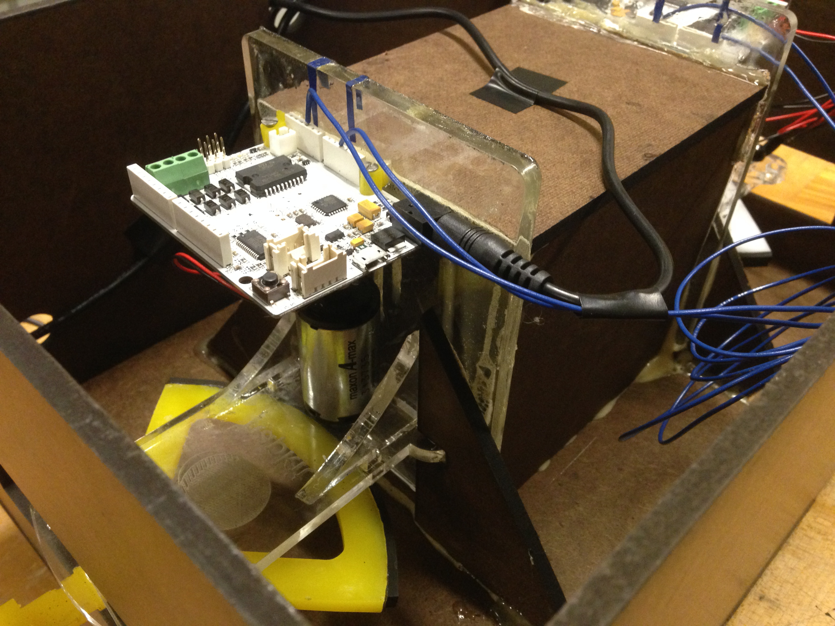
Main board and secondary board electronics
General Design
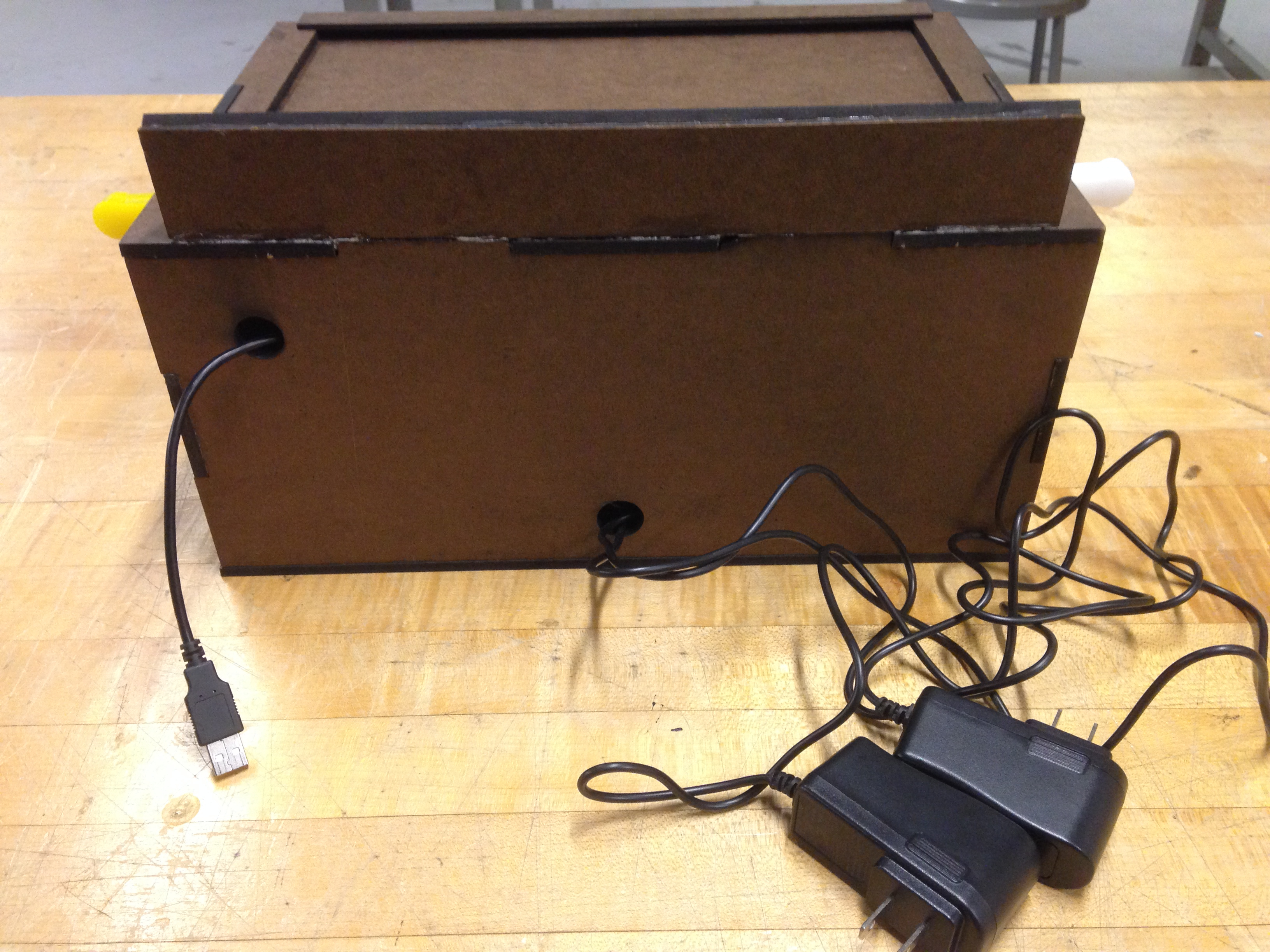
The two boards communicate with each other directly. The output from the magnetoresistive sensor on the secondary board is sent directly to an input pin on the main board. The motor wires on the secondary board are connected directly to output pins on the main board. Ground on the secondary board is connected to ground on the main board. The main board communicates with the computer via a USB cable, and each board is connected to a power source.
Electronic Challenges
We tried many different approaches before settling on our final design. At first, we were adamant about processing the position and motor data for the second board on the second board itself. We tried to connect the two boards using the Arduino Wire Library, but it was too slow. We then tried to output the second board's paddle positions via an analog output and tried transferring information by using Strings, ints, doubles, and bytes. Again it was too slow. Finally, we realized that it would be faster to do all the communication and information processing on one board. We found beauty in simplicity and settled on the approach explained above.
Building The Project
- Connect the A5 pin on the main board to the A2 pin on the secondary board.
- Connect ground on the main board to ground on the secondary board.
- Connect the motor wires for the second board's motors to the secondary motor pins on the main board.
- Connect the main board to the computer via a USB cable.
- Plug each board into a power source.
Hardware
Summary
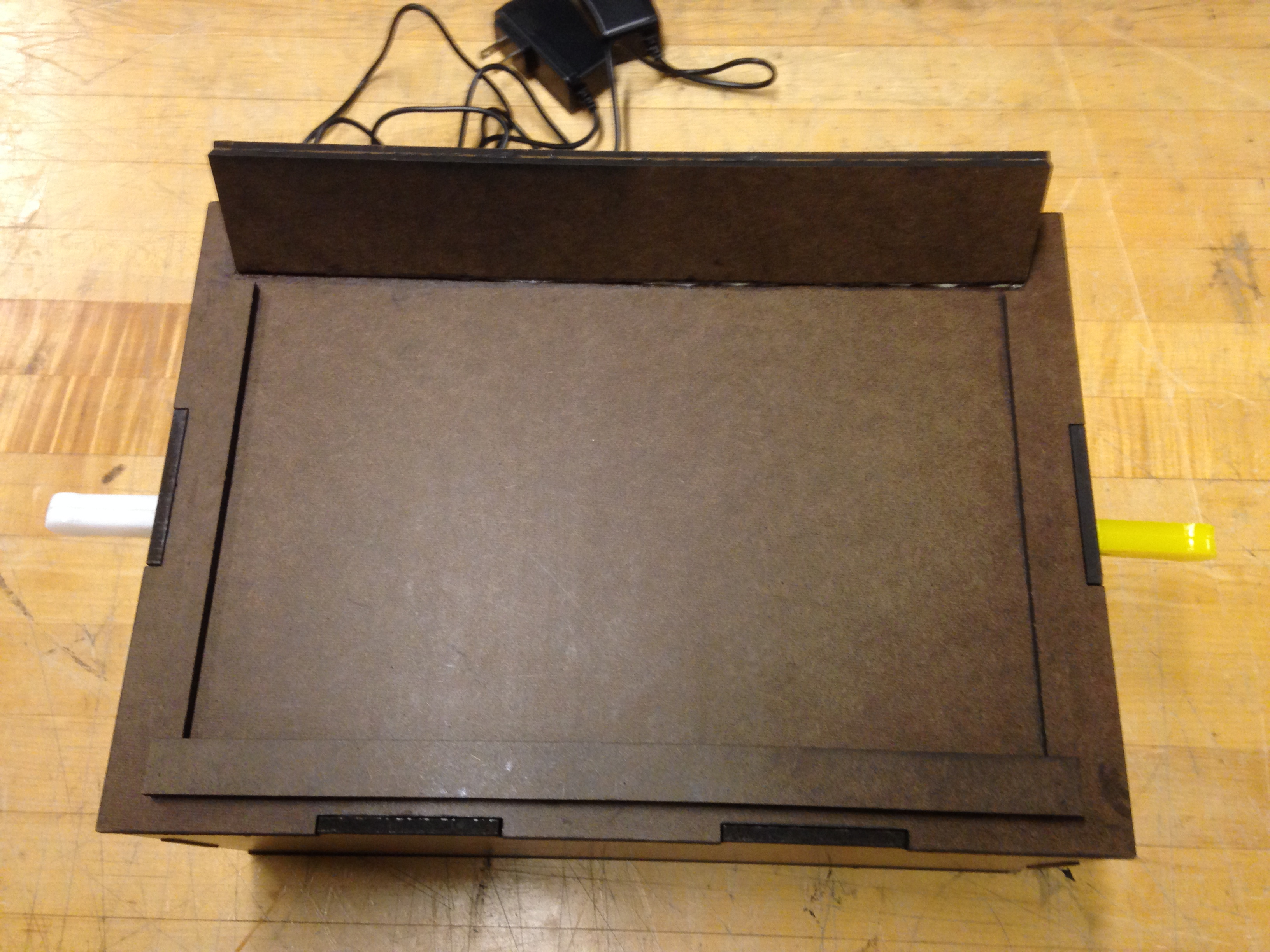
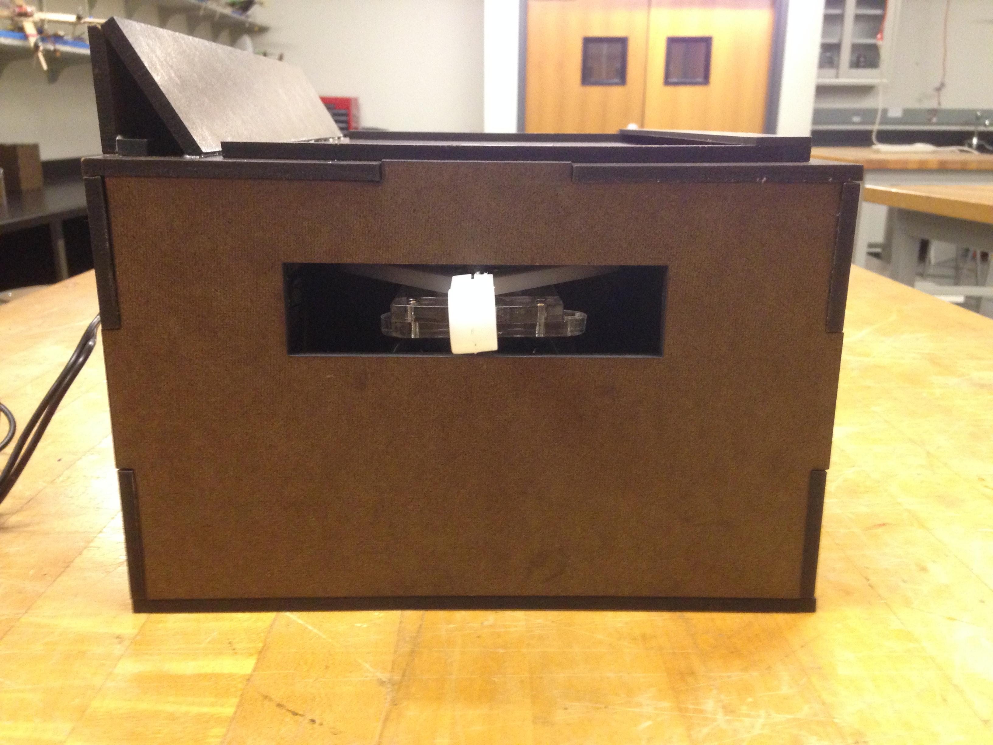
The basic layout of our project consists of two Hapkits mounted inside a box that supports the weight of a laptop which functions as a display for the game.
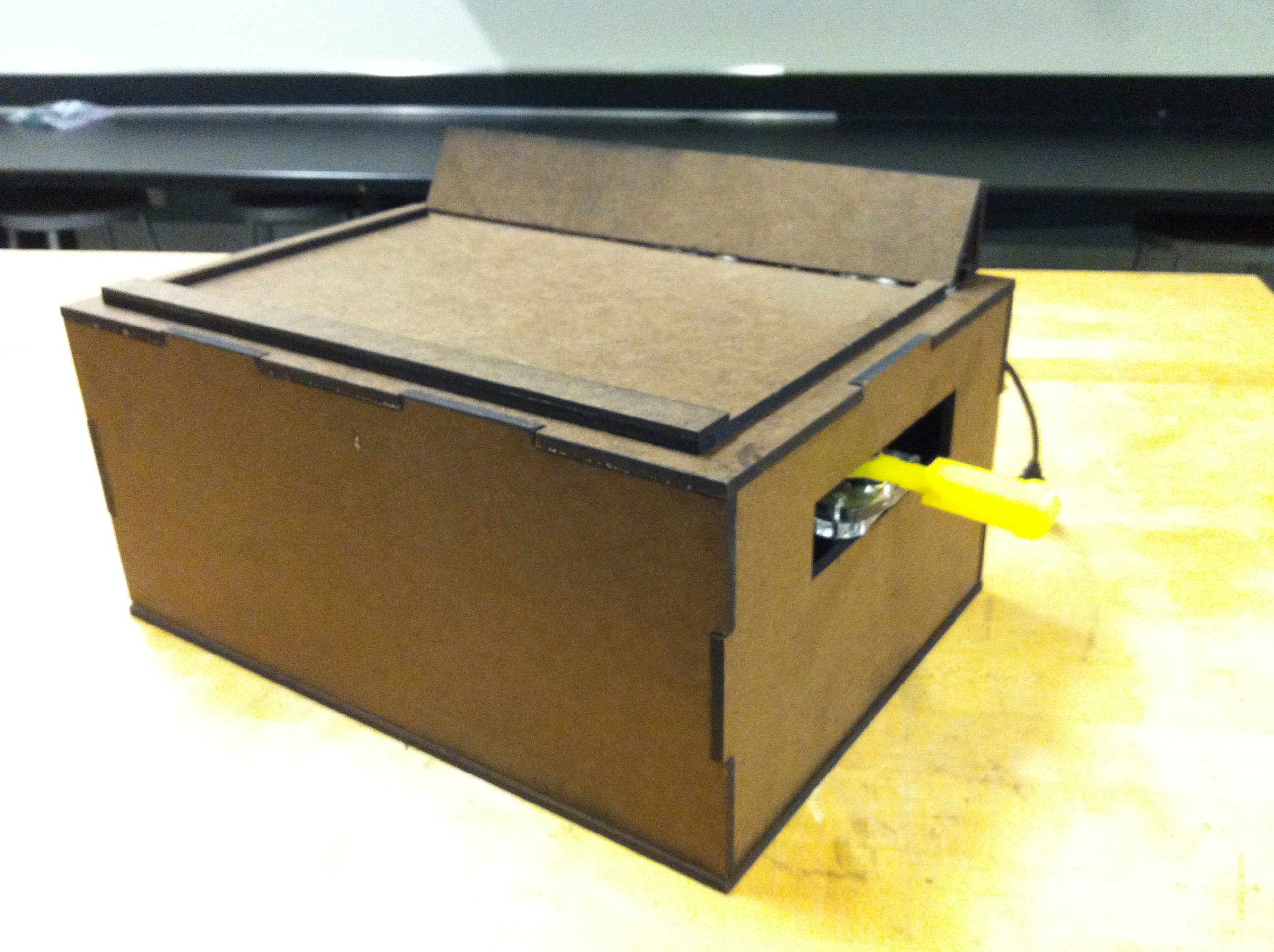
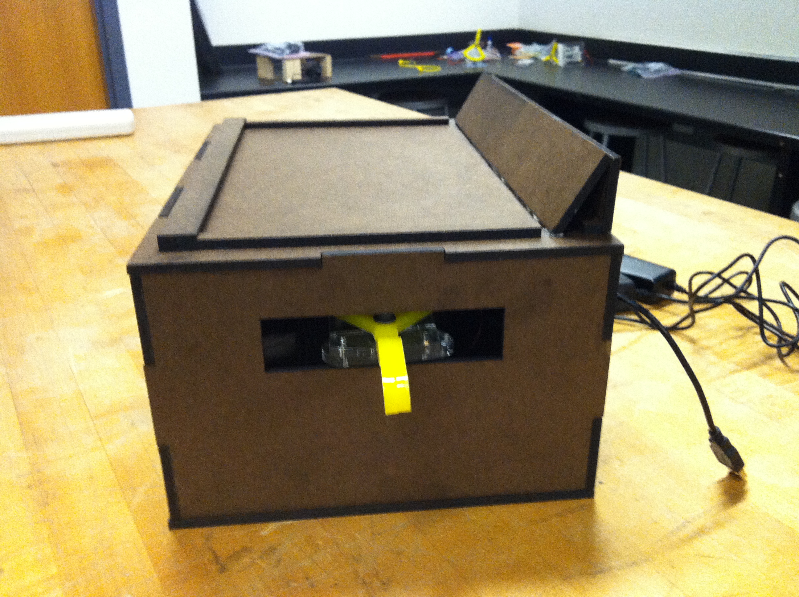
Box
Because the motors of the Hapkits output enough force to inhibit a user's movement when a power up is activated, the mounting of the box must be very secure. For this reason, the box in which the Hapkits are mounted has puzzle-like notches along each edge in order to increase surface area of the adhesive holding the box together (if duron is used as material, wood glue works well for this portion of construction).
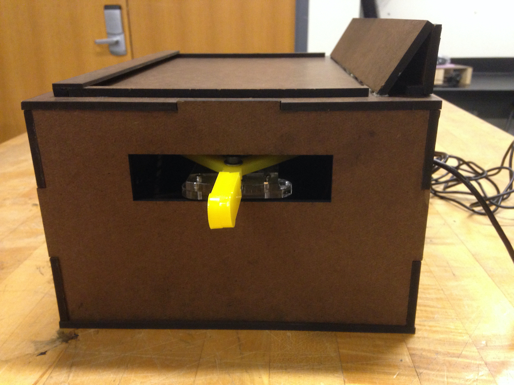
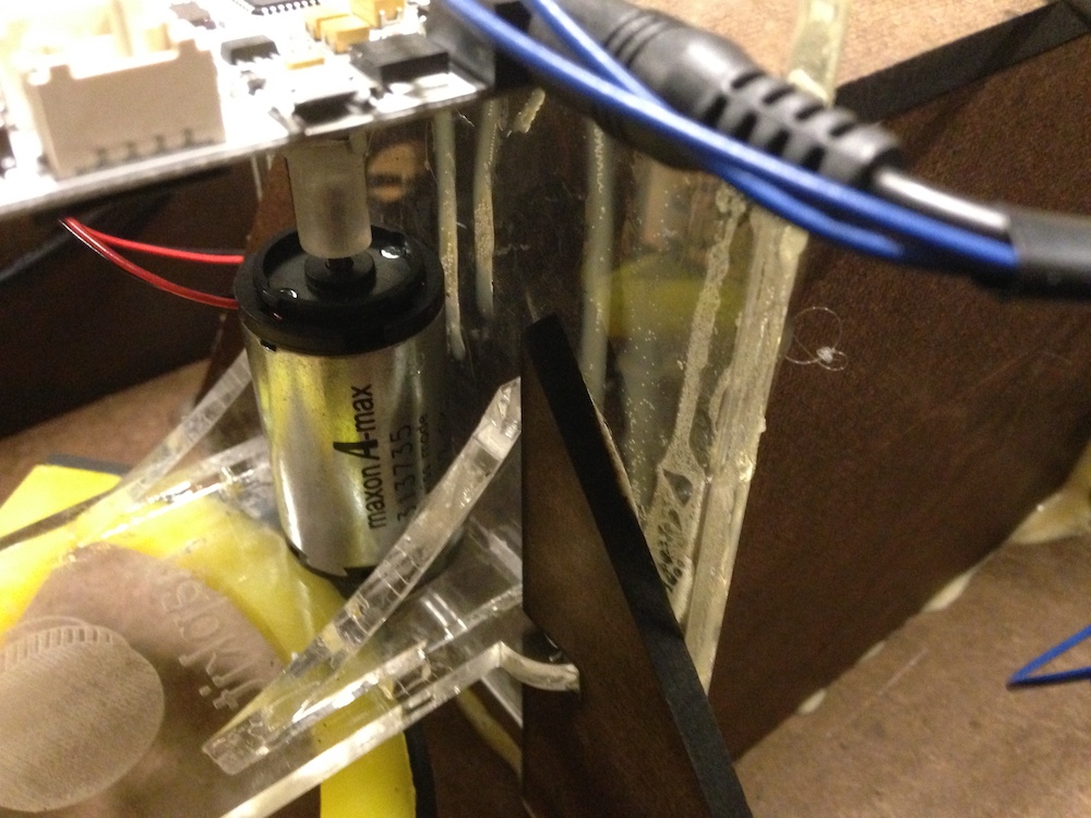
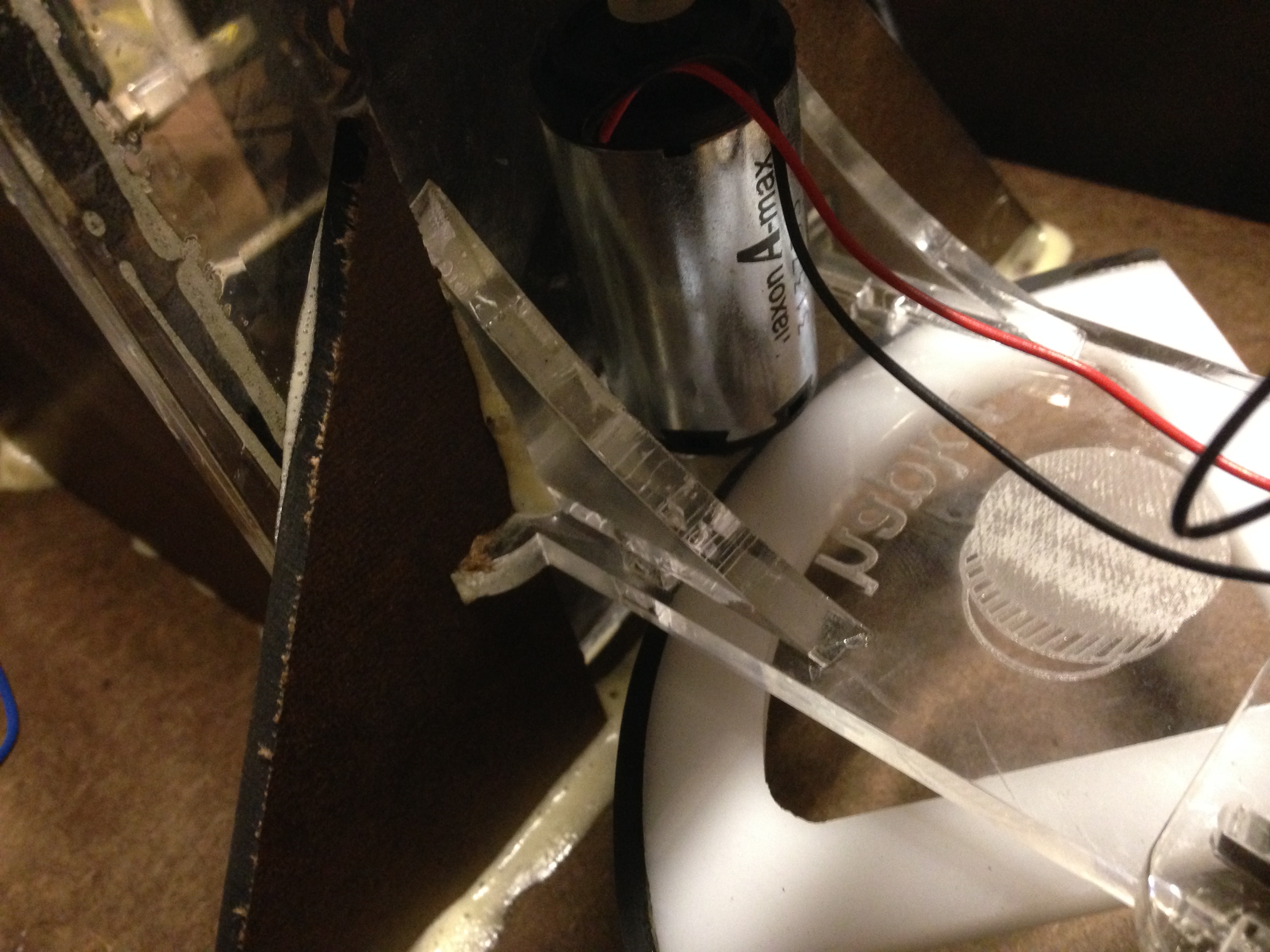
Hapkit Mounts
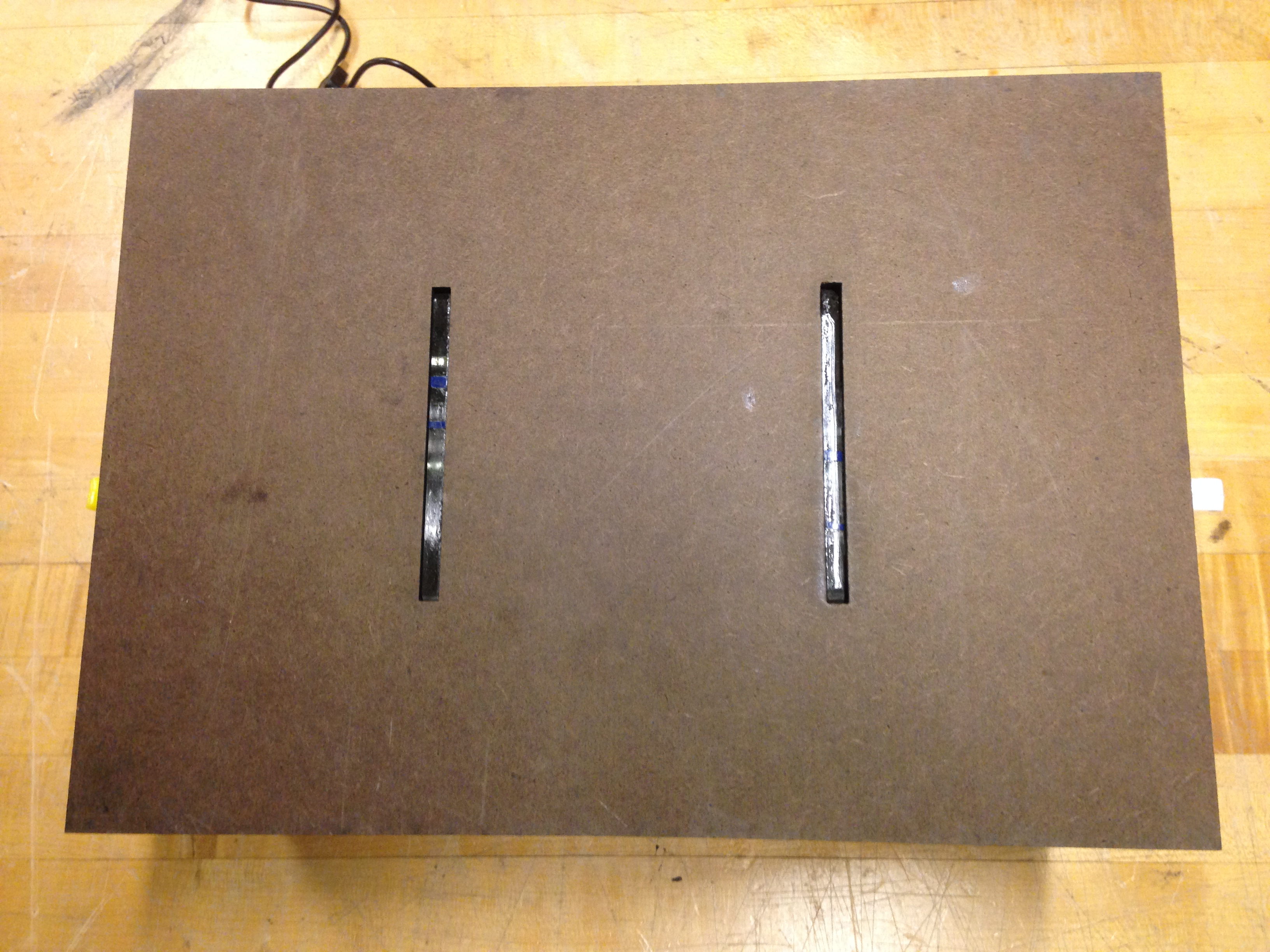
Securing the Hapkits within the previously described box involves several steps. The first step is gluing the triangle supports to the top of the baseplate of the Hapkit (the side that the paddle is mounted to). If the triangle supports are properly dimensioned, the notches should fit into the edge of the acrylic piece that connects the paddle of the Hapkit to the base of the Hapkit. The base of the triangle should be flush with the edge of the Hapkit's baseplate so that when the Hapkit is placed within the box with the handle of the paddle sticking through the square hole in the ends of the box, the triangles help support the Hapkit. The next step is to place a support block inside the box, between the two Hapkits. The support block consists of two sides and a top, which should be glued to the base plate of each hapkit and the surface of the box they rest on. This surface will be the surface that the laptop will rest on once construction is finished. The dimensions of the support block are such that the distance between the paddle of the Hapkit and the side of the box allows for complete range of motion for the rotating paddle, but prevents it from rotating so far so as to lose contact with the axle of the motor. This is very important because if the motor spins without contact with the Hapkit paddle, the virtual paddle on the display will be moved off the screen. The final step of securing the Hapkits within the box is to place the base on the bottom of the box. Notice there is enough space between the base and the Hapkit board to allow the wires connecting the two Hapkits to plug into the Hapkit boards without preventing the base from fitting snuggly on the baseplates of the Hapkits.
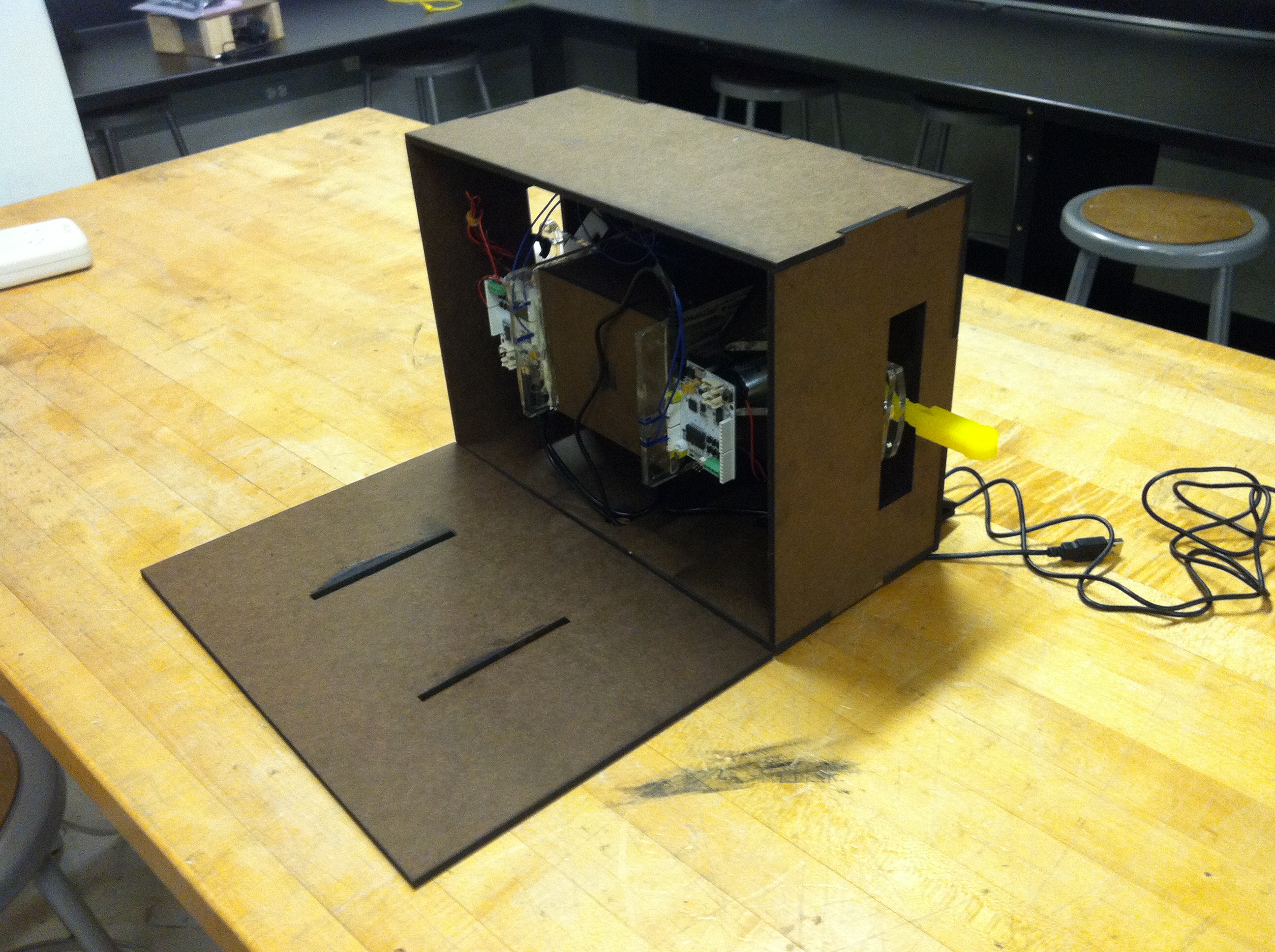
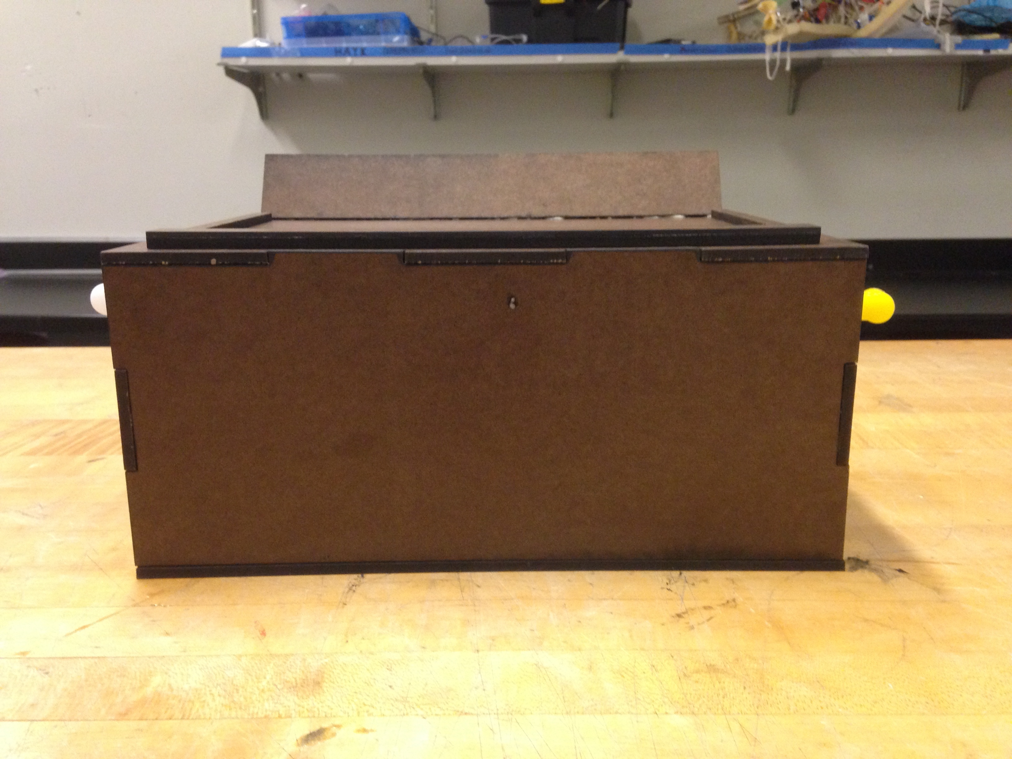
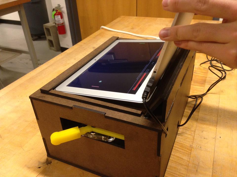
Display Mount
In order to secure the laptop on the top of the box, thin rectangles of material are placed along three sides of the laptop (the side which the keyboard is attached to is left alone for now). Those boards will be referred to as support boards, and once they are glued to the top of the box, a thin piece of material (in our case, 1/8th in duron) is glued on top of the long computer support board so that it latches over the display of the laptop. This prevents the laptop from tipping over. The bottom of the laptop is supported by rectangles of duron glued such that they form a triangular prism, further supporting the laptop and preventing it from toppling off the box. If the prism is spaced correctly, the laptop should be able to slip in and out of the mount. Securing the laptop to the top of the box is heavily dependent on the specific laptop that will be used. The pictures of the laptop mounting included in this page will be most useful for getting a rough idea of what it should look like. Depending on the laptop being used, modifications can be made as needed.
Hardware Challenges
One difficulty we had with the hardware was that when users were actually playing Haptic Battle Pong, the power-ups sometimes applied large forces on the Hapkit paddles. The position of the virtual paddle is determined by calculating the number of times the axle of the motor is rotated as the physical paddle is moved. A few times, when very large forces were applied and the user tried to move the paddle very quickly at the same time, the paddle on the screen sometimes became uncalibrated and disappeared off the side of the screen. These inconsistencies were due to the relatively inexpensive magnetoresistive sensor, which reports the number of rotations of a magnet on the end of the motor's axle. The axle rotated so quickly that the sensor lost count. The rare times this occurred, we reset the Arduino software, which is done by hitting a keyboard shortcut that is described in the software section. Resetting the software did not adversely effect gameplay and the game continued without much trouble.
Functionality
In Haptic Battle Pong, each player controls a single paddle and the main objective is to bounce the ball off of the paddle in order to not lose life points. The secondary objective is to avoid letting power-ups hit one's virtual paddle. Power-ups are sent by hitting power-up bricks. When a player is hit by a power-up, they lose life points and feel a corresponding haptic effect.
When a user's virtual paddle is struck by the ball, the handle they are physically holding onto exerts a force onto their hand which mimics the feeling of actually hitting a ball with a paddle. When a player's virtual paddle comes in contact with a power-up, the user will feel a specific force that inhibits their ability to physically move their paddle in a desired direction. There are four haptic-effect-driven power-ups. There is a power-up that causes a force that pushes the player's paddle upwards. There is one that causes a force that pushes the player's paddle downwards. The third power-up causes a dampening effect on the player's paddle which impedes the user's movement in either movement with a force that is a function of the user's paddle's velocity. And the final power-up causes a seemingly random force that moves the player's paddle in one direction and then the other. If a player successfully hits their opponent with one of their power-ups, any force they would be feeling is eliminated.
The device functioned almost completely as designed, except for once in a while the virtual paddle would move off the screen because the magnetoresistive sensor would lose count of the rotations of the magnet on the end of the motor's axle. As a result, the program would lose track of the position of the player's paddle. We received very positive feedback during the open house, and the only comment that implied that we could improve the design was that the paddle shouldn't move off the screen, which can easily be fixed by using a more accurate (and expensive) sensor in place of the magnetoresistive sensor. The most technical question we received was if our device "updated" faster than 500Hz (the "magic number" for producing very realistic haptic feedback), which it doesn't simply because the time it takes for the two Hapkits (which utilize what is essentially an Arduino Uno board) to communicate slows down the update rate.

Having fun! Always important.
Files
Files ending in .ino.zip are Arduino code files, those ending in .pde.zip are Processing code files, those ending in .ai.zip are Adobe Illustrator files (which should be able to be opened on any computer capable of viewing pdf files), those ending in .zip are Solid Works files.
Cost Sheet
Software
Hardware
- Attach:HapticBattlePongTriangleBrace.zip This is the CAD of the triangles used to secure the hap kits to the interior of the box (as seen in the picture in the Hapkit Mount section
- Attach:HapticBattlePongTriangleBrace.ai.zip
- Attach:HapticBattlePongSupportBlock.zip This is the CAD file for the support block between the two Hapkits within the main box as referenced in the Hapkit Mount section.
- Attach:HApticBattlePongSupportBlock.ai.zip
- Attach:HapticBattlePongDeviceHousing.zip This is the CAD file for the main box as seen in the Hardware section, subsection Box.
- Attach:HapticBattlePongDeviceHousing.ai.zip
- Attach:HapticBattlePongAngledComputerSupportBoard.zip This is the CAD file for the board that supports the base of the laptop at an angle as seen in the Hardware section, subsection Display Mount.
- Attach:HapticBattlePongAngledComputerSupportBoard.ai.zip
- Attach:HapticBattlePongAngledComputerSupportBoard.zip This is the CAD file for the thin piece of Duron which holds the display down once it is slid into the computer support boards as seen in the Hardware section, subsection Display Mount. This piece is the vertical portion of the triangular prism mentioned in Display Mount.
- Attach:HapticBattlePongAngledComputerSupportBoard.ai.zip
- Attach:HapticBattlePongComputerSupportBoards.zip This is the CAD file for the Computer Support Boards which are referenced in the Hardware section, subsection Display Mount, they can also bee seen in the pictures in the same section.
- Attach:HapticBattlePongComputerSupportBoards.ai.zip
- Attach:HapticBattlePongComputerBaseSupport.zip This is the CAD file for the board that supports the base of the laptop as seen in the Hardware section, subsection Display Mount. This piece makes up the angled component of the triangular prism mentioned in the Display Mount Section.
- Attach:HapticBattlePongComputerBaseSupport.ai.zip